This thread has been locked.

If you have a related question, please click the "Ask a related question" button in the top right corner. The newly created question will be automatically linked to this question.

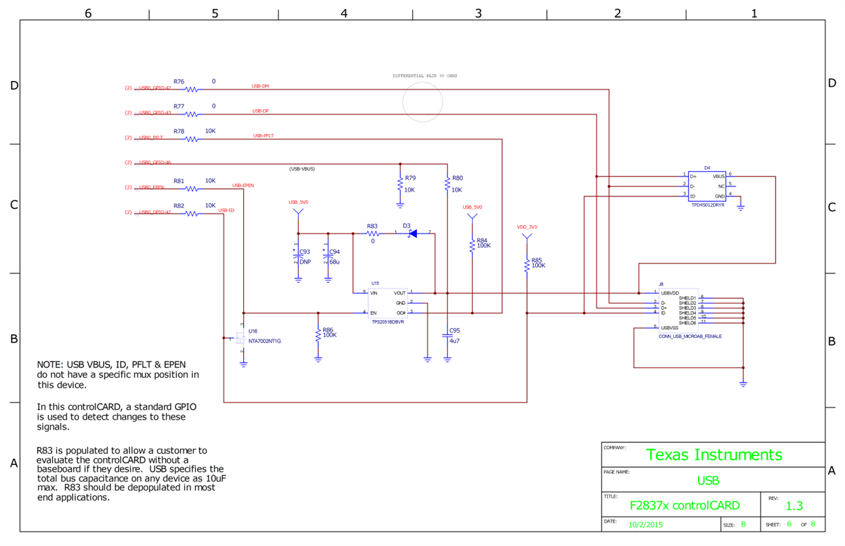
TMS320F28377D: I have a question about the USB circuit of the F28379D ControlCARD.

Part Number: TMS320F28377D

Hi,

I am trying to design a USB communication circuit based on the TMS320F28377D.

So I am looking at the USB circuit of the F28379D ControlCARD.

In the attached circuit, The 5V level signals are connected to the GPIO ports of 28X chip through USB-VBUS, USB_FLT lines.

As far as I know, the 28X chip's GPIO port allowable voltage range is from GND to VDDIO (3.3V).

Is it okay to design the circuit similar to the F28379D ControlCARD?

I would like to know if there is a reference circuit that connects the USB Type-A connector to the USB communication port of the TMS320F2837x chip.

  • Hi,

    You're correct about the GPIO voltage concern. Please see the below snippet from the TRM USB section. The schematic of the F28379D ControlCARD is a little different than what's presented, as it uses a power distribution switch to limit the current.

    Are you planning on using the standard Type-A connector, which is 4-pin rather than 5-pin (mini/micro)?

    Please see the USB section within the TRM, specifically section 23.2 "Features" for some further guidance. http://www.ti.com/lit/spruhm8

    Best,

    Kevin

  • Thank you for your quick response.

    Yes, I would like to use the same 4-pin USB Type-A connector as the attached image. After designing the USB circuit on the TMS320F2837x system, I want to back up the data by connecting the USB mass storage device.