Tool/software: Code Composer Studio
Dear Ti community
I'm developing PCMC on HVPSFB.
To understand FET switching timing,I made time chart.
I insert DCAEV1 the middle of EPWM1 up count and down count.
(SR_mode = 2)
But,the time chart was as follows.
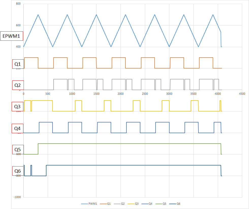
Q2,Q3,Q5,Q6 are strange.
So,I want you to point a mistake out.
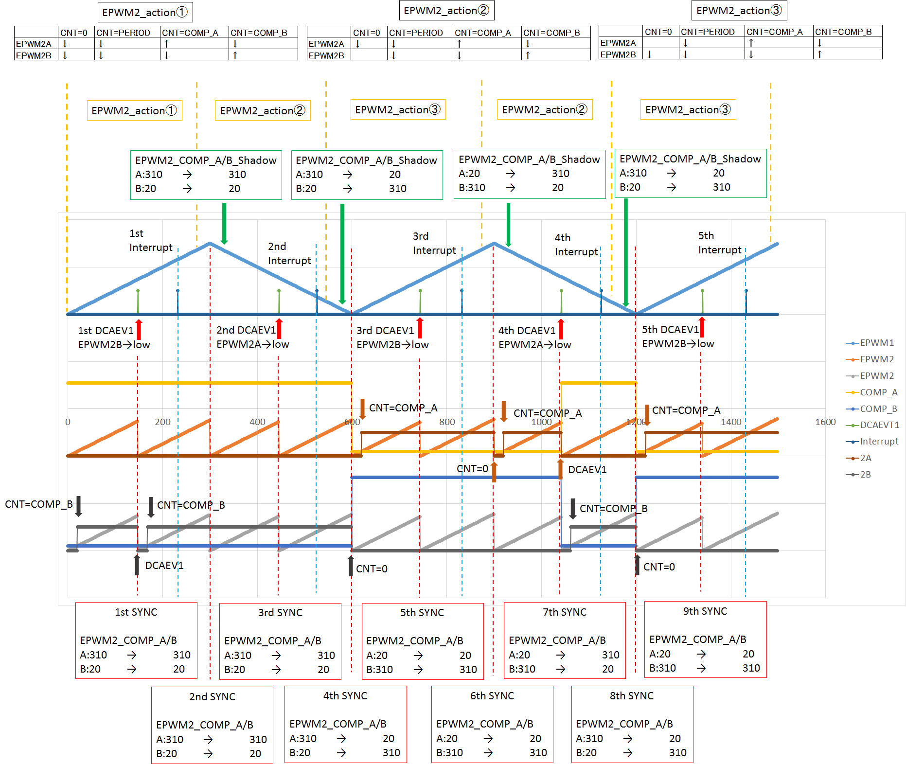
- About Q2,Q3.
First,COMP_A = 310,COMP_B = 20.
Count up EPWM2_CNT and soon,EPWM2_B is high because of COMP_B match.
After that EPWM2_B is low because of 1st DCAEV1 and soon be high because of COMP_B match.
Then,1st interrupt start and EPWM2_action change.
COMP_A/B_Shadow don't change(A:310→310 B:20→20), so COMP_A/B don't change at 3rd SYNC.
Then 2nd interrupt start and EPWM2_action change.
Before 4th SYNC , COMP_A/B_Shadow change(A:310→20 B:20→310), so COMP_A/B change at 4th SYNC.
At 4th SYNC,EPWM2_B is low because of CNT = 0.
And soon ,EPWM2_A is high because of COMP_A match .
Then 3rd interrupt start and EPWM2_action change.
At 6th SYNC,EPWM2_A is low because of CNT = 0.
And soon ,EPWM2_A is high because of COMP_A match .
After 6th SYNC,EPWM2_COMP_A/B_shadow change(A:20→310 B:310→20).
COMP_A/B change at 4th DCAEV1 and EPWM2_A is low because of 4th DCAEV1 .
And soon ,EPWM2_B is high because of COMP_B match .
Then 4th interrupt start and EPWM2_action change.
Before 8th SYNC,EPWM2_COMP_A/B_shadow change(A:310→20 B:20→310).
So COMP_A/B change at 8th SYNC and EPWM2_B is high because of CNT = 0 .
And soon ,EPWM2_A is high because of COMP_A match .
・・・
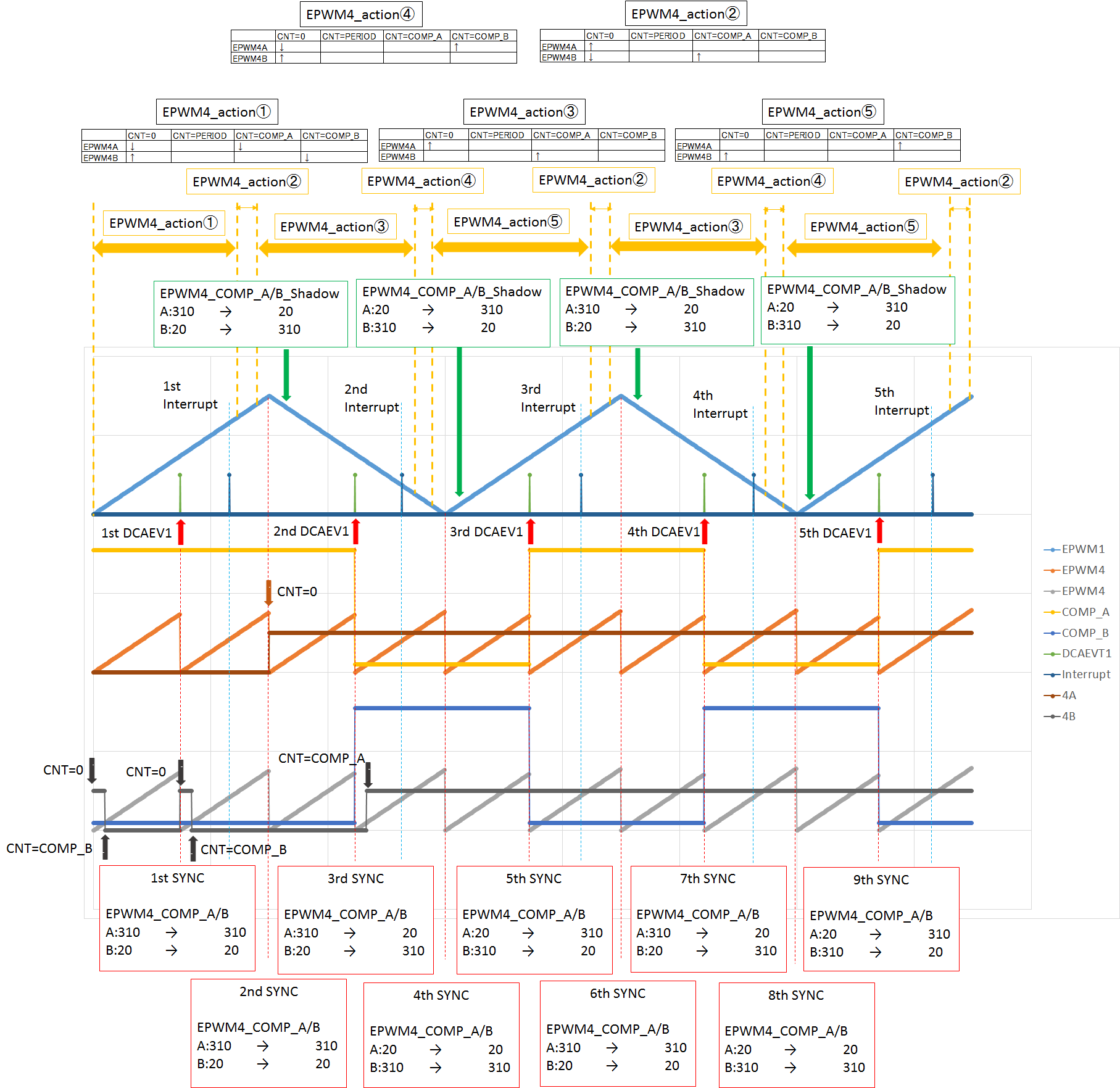
- About Q5,Q6
First,COMP_A = 310,COMP_B = 20.
When count start ,EPWM4_B is high because of CNT = 0.
And soon , EPWM4_B is low because of COMP_B match.
At 1st DCAEV1 , EPWM4_B is high because of CNT = 0.
And soon , EPWM4_B is low because of COMP_B match.
Then,1st interrupt start and EPWM4_action change.
And soon EPWM4_action change before 2nd SYNC.
At 2nd SYNC , EPWM4_A is high because of CNT = 0.
After 2nd SYNC, EPWM4_COMP_A/B_shadow change(A:310→20 B:20→310).
At 2nd DCAEV1 , COMP_A/B change,and soon EPWM4_B is high because of COMP_A match.
After that, EPWM4_A/B don't change.
Because the condition to be low EPWM_A/B is only when CNT = 0 between interrupt and SYNC(that means EPWM4_action②,④).