This thread has been locked.

If you have a related question, please click the "Ask a related question" button in the top right corner. The newly created question will be automatically linked to this question.

CCS/TMS320F28035: HRPWM for Phase Shift Full Bridge

Part Number: TMS320F28035

Tool/software: Code Composer Studio

Hello,

we have are using a TMS320F28035 to generate the PWM pattern for a full bridge driven in Phase Shift Modulation @ 100 kHz. The application is: battery charger.

At such frequency, with standard pwm, the phase can be modualted with 2x16,6 ns steps: the resulting resolution is not enough to accurately regulate the charging current in Average-Current-Mode-Control, therefore we are trying to use the HRPWM function.

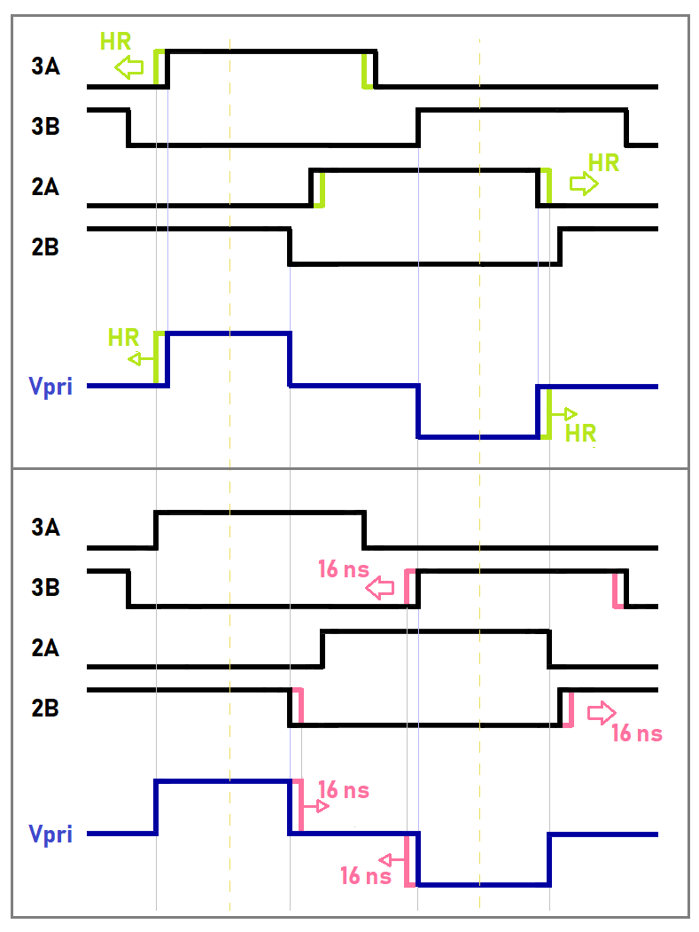
We have seen that HRPWM is available only of A-type pwm: being the two high-side fets driven by A-type pwm, and the two low-side fets driven by B-type pwm, we will have high resolution only on the high-side fets: will it be effective ?

Then: in our first tests we have seen that only one of the two wavefronts of the A-type pwm is shifting with high resolution, while the other one shifts with standard 16,6 ns steps. I think this will make HRPWM ineffective or even dangerous because of xformer imbalance. Why does it happens ? How can we make both pwm wavefronts move with high resolution ?

Thanks for answers

  • Hi Davide,

    I am looking into this and will get back to you tomorrow.

    Regards,
    Chen
  • Thank you Chen.

    we have just addressed the wavefront issue: now both Low-to-High and High-to-Low wavefronts are regularly shifting. Therefore we have the two high-side pwm's that shift with HR and the two low-side pwm's that shift with standard resolution (+/- 16 ns).

    The result is shown in the following picture:

    While the two A-pwm's are shifting within the 16 ns interval (green) the B-pwm's do not shift, and the trafo primary voltage wavefronts are no more symmetrical with respect to the vertical axis: that will not produce a Vxs imbalance therefore its should not be an issue.

    Then the two B-pwm's will make a 16 ns "jump" (pink), and the trafo primary voltage wavefronts will become symmetrical again with respect to the vertical axis.

    That "jump" is not much good.... any idea to resolve this issue ?

    Thanks

  • Hi Davide,

    Sorry, I don't get it why you need to do the phase shift for 3A and 3B. I thought 2A and 2B are doing the phase shift only. Can you also explain what exactly does "jump" refer? When does this Jump happen? Does it happen instantly after the HR shift? Thanks.

    Regards,
    Chen
  • The left-leg pwm's (2A for upper fet and 2B for lower fet) should shift with respect to the right-leg pwm's (3A for upper fet and 3B for lower fet). I can set, for example, HR resolution 16 times finer than standard resolution: therefore 2A and 3A will shift with 1 ns step, and only after 16 steps I will get a coarse 16 ns step-shift ("jump") on 2B and 3B. Did I clarify ?

  • Hi Davide,

    I will be back to office on 3/21 and will follow this thread at that time. Sorry for the inconvience.

    Regards,
    Chen
  • Hi Davide,

    I am very sorry for the late catch up.
    Please take a look at this thread. This can realize both HRPWM for A and B for F28035 if you still have enough EPWM modules available. Let me know if this can help solve the problem you have.
    e2e.ti.com/.../252985

    Regards,
    Chen
  • Hi Davide,

    I am going to close this thread now since I don't get any updates from you. But feel free to come back if you have any questions regarding to this issue. Thanks.

    Regards,
    Chen
  • Hi Chen,

    the answer from Hrishi Nene didn't resolve my issue because 2A, 2B, 3A & 3B are the only pwm's currently available on my control board.
  • Hi Davide,

    Ok, thanks for your updates. Then it might be a little bit complex, I will get back to you later to see if I have any other suggestions. Also I would like to mention that our new device f2837x and f28004x support HRPWM for both A & B channels although it might not help you out in your specific case.

    Regards,
    Chen

  • Chen,

    in his design "Bidirectional 400V-12V DC/DC Converter Reference Design" (www.ti.com/.../TIDM-BIDIR-400-12) Hrishi Nene uses both A & B pwm's for PSFB in the same way as I did. Therefore I suppose he also could not to implement HRPWM.
    Whereas both applications are "bettery charger", the question is: how he managed to regulate the charging current with good accuracy in Average Current Mode Control without using HRPWM ? (...maybe me too I can do without it...)

    Regards
    Davide

  • Hi Davide,

    I think you can try to use the standard PWM like Hrishi did in "Bidirectional 400V-12V DC/DC Converter Reference Design" based on the sample code and the user guide. And standard PWM is usually enough for 100kHz switching frequency. HRPWM is usually targeted for more than 500kHz. Thanks.

    Regards,
    Chen