


Part Number: TMS320F28335
Dears:
From the below picture we can use 50MHz as input clock.

However, from the below picture the crystal is limited in about 30MHz.
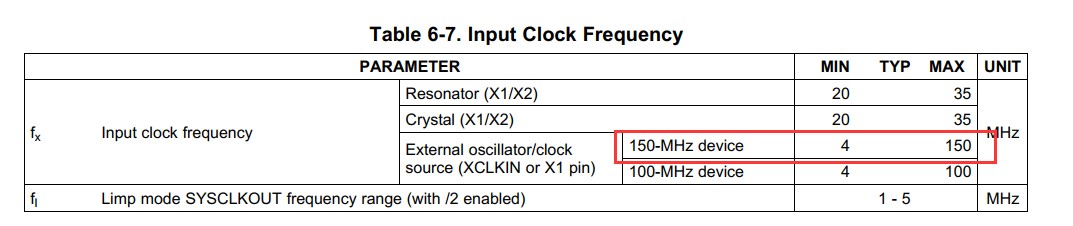
How can we design to get the 150MHz frequency?
Pls. kindly help to give some advice.
Part Number: TMS320F28335
Dears:
From the below picture we can use 50MHz as input clock.
However, from the below picture the crystal is limited in about 30MHz.
How can we design to get the 150MHz frequency?
Pls. kindly help to give some advice.
