This thread has been locked.

If you have a related question, please click the "Ask a related question" button in the top right corner. The newly created question will be automatically linked to this question.

CCS/TMS320F28027: HV-PSFB Open Loop Testing of Example code

Part Number: TMS320F28027

Tool/software: Code Composer Studio

Hi,

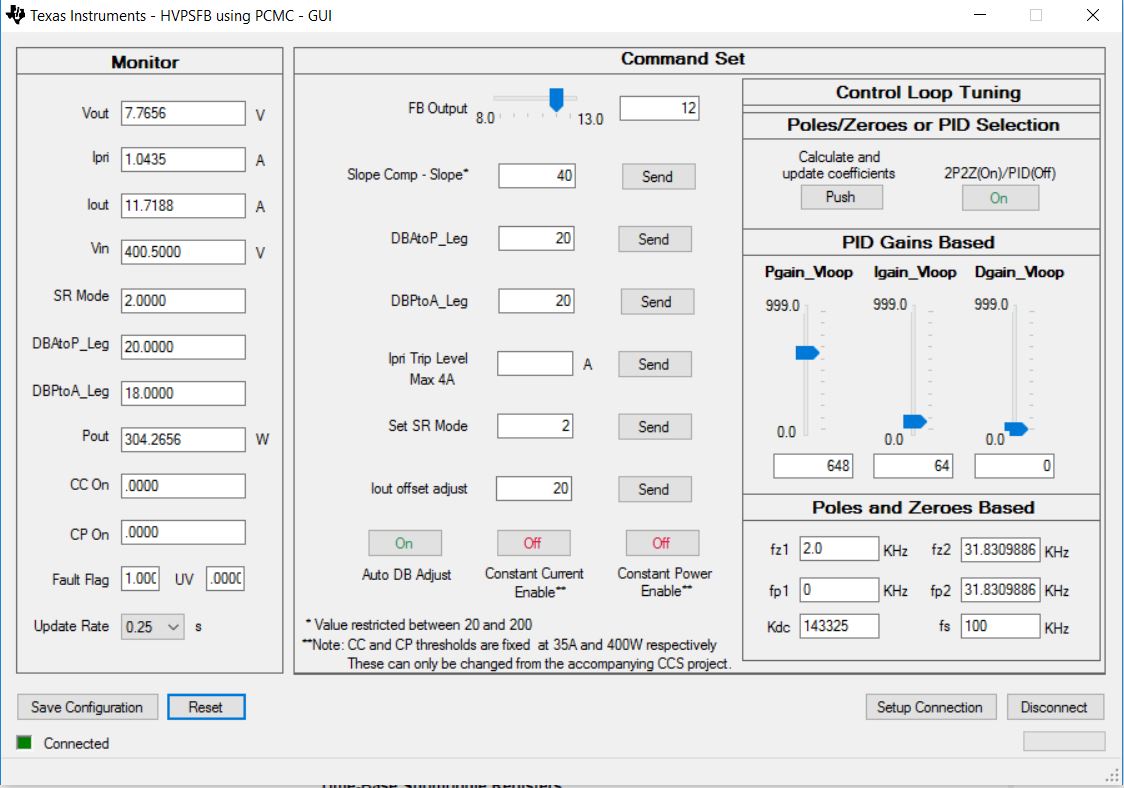
I am trying to analyse and test the Peak Current Mode Control code (HV-PSFB) in open loop by providing the Iout, Ipri, Vin and Vout signals to the MCU, but I don't get any PWMs out of the microcontroller. For the voltage signals I use a DC voltage generator (~2V) and for the current signals I generate sawtooth signals (top one - Iout, middle one - Ipri, last one - Vout), as it can be seen on the attached screenshot. At the GUI I noticed that the Fault Flag is 1.00, but I am not sure why the fault is high, since I haven't done any changes in the code.

Do you have any ideas why I don't see any PWMs coming out of the microcontroller and how can I resolve it?

Thanks.

  • Ivan,

    Please see the following post https://e2e.ti.com/support/microcontrollers/c2000/f/171/p/714212/2635464#2635464  There is a known bug in this code, and a corrected version is supplied in this thread(from TLEE about half way down).  Let me know if the new .out file solves your issue.

    Best,

    Matthew

  • Hi Matthew,

    Unfortunately, this does not resolved my problem. I followed the steps but still the Fault flag is 1.00. Please, refer to the attached screenshots.

    Thank you.

    Regards,

    Ivan

  • Hi, user5875413,

    It seems like you triggered the current protection. Can you try to lower your Ipri amplitude? The peak value is more than 2V in your figure.

    Regards,
    Chen
  • Hi Chen,
    Thank you for your suggestion. Unfortunately, even if I lower the Ipri peak to 0.5V my Fault flag is still high. Currently, I am feeding the Ipri signal to pin8 of J1 and a DC voltage to pins 6 and 7 of J5 feeding the Vout and Vin respectively. Based on the User's guide this should be sufficient to evaluate the operation of the code and to generate the PWMs, am I correct?

    What could be the potential reasons for tripping the fault flag to high?
    Thank you!
    Kind regards,
    Ivan

  • Hi user5875413,

    I suggest to check your current ADC sensing in the expression window. You can set a relatively large trip value first and to observe whether the sensing value makes sense.

    Also according to the build 1, you are suggested as below in the user guide:
    25.
    Power the input at J1, J2 with 400V DC.
    26.
    Increase the peak current reference command by setting Gui_IfbSet to a higher value 0.25(say) in the watch view. The output voltage should increase. Observe the output voltage carefully, this should not be allowed to exceed the capabilities of the board. Keep in mind that when operating with a certain Gui_IfbSet value if the load is suddenly reduced, the output voltage will go up. Therefore do not make any sudden changes of load or big increases in Gui_IfbSet command when operating in build 1.
    27.
    Observe the different ADC results in the watch view for different Gui_IfbSet values.

    Regards,
    Chen