This thread has been locked.

If you have a related question, please click the "Ask a related question" button in the top right corner. The newly created question will be automatically linked to this question.

CCS/TMS320F28379D: How to synchronize two or more TMS320F28379D?

Part Number: TMS320F28379D

Tool/software: Code Composer Studio

Hi All,

I'm working on paralleling two or more inverters.

Here I'm trying to synchronize the PWM generated by two control cards. Following the Manual of TMS320F28379D, one device act as master to send the syncout signal to the slave one through GPIO. The ePWM module in the slave device will receive the synchronizing signal through GPIO15 which can be selected from INPUT5. The INPUT5 will be the SYNCIN source in ePWM module.

The related codes are as follows,

Master:

//***********Main codes in EPWM***********************

EPwm1Regs.TBCTL.bit.SYNCOSEL = TB_CTR_ZERO;  

SyncSocRegs.SYNCSELECT.bit.SYNCOUT = 0;   //EPWM1SYNCOUT

//*****************GPIO****************************

GpioCtrlRegs.GPAPUD.bit.GPIO6 = 0; // Enable pullup resistor

GpioCtrlRegs.GPAMUX1.bit.GPIO6 = 3; // Set GPIO6 to SYNCOUT

GpioCtrlRegs.GPADIR.bit.GPIO6 = 1; // set as output

============================================

Slave:

//***********Main codes in EPWM***********************

EPwm4Regs.TBSTS.bit.SYNCI = 1;

EPwm4Regs.TBCTL.bit.SYNCOSEL = TB_SYNC_IN; 

SyncSocRegs.SYNCSELECT.bit.EPWM4SYNCIN = 5;    // SYNCIN Source: EXTSYNCIN1

EPwm4Regs.TBCTL.bit.PHSEN = TB_ENABLE;

EPwm4Regs.TBPHS.bit.TBPHS = 1;

//*************************GPIO****************************

InputXbarRegs.INPUT5SELECT = 0x15;  // Connect INPUT5 to GPIO15

GpioCtrlRegs.GPAPUD.bit.GPIO15 = 0; // Enable pullup resistor

GpioCtrlRegs.GPAMUX1.bit.GPIO15= 0; // Set GPIO15

GpioCtrlRegs.GPADIR.bit.GPIO15 = 0; // set as input

====================================================

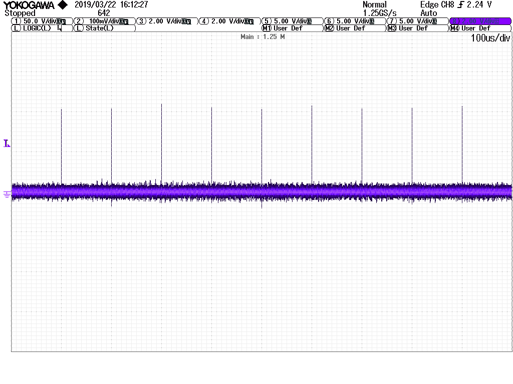
I observed the GPIO6 in GPADAT register and it shows 0. It seems the SYNCOUT didn't transfer the signal to the output of master device, which command is missing?

Thanks. 

  • Hi Jiacheng,

    I think the first step is definitely to observe the syncout signal on GPIO6.

    You may need an 'EALLOW;' statement before writing to the GPIO config and other mux select registers. If the writes are failing due to access protection, you can run that segment of code using the debugger, then use the expressions window to verify that the bits are getting set as expected.

    Is ePWM1 creating a waveform on the pins? If it isn't you may want to do something like toggle one of the ePWM GPIO on zero count to confirm the ePWM is running as expected.
  • Hi Devin,

    Thanks for the answer. There is a 'EALLOW' command before the GPIO config commands.

    I also added the 'EALLOW' before

    SyncSocRegs.SYNCSELECT.bit.SYNCOUT = 0; //EPWM1SYNCOUT

    The SYNCOUT signal from GPIO6 is displayed on the oscilloscope:

    We can see the sync pulse every 100us which is the expected waveform. Initially, I just observed the numerous value in the CCS interface.

    As for the slave device, I couldn't observe the same waveform from GPIO15. 

    Also, is the INPUT5 the source of EXTSYNCIN1 by default? I didn't find the register to select the source of EXTSYNCIN1.

    Thanks.

    Jiacheng

  • Hi Jiacheng,

    EXTSYNC1 will always use INPUT5. You don't need to select that INPUT5 is the source of EXTSYNC1, but you do need to select the source of INPUT5 to be whatever GPIO you are using as the input SYNC.

    Note that it looks like you've maybe set INPUT5 source as '0x15' = GPIO21 and maybe you want INPUT5 sourec = '15'?

    Another strategy you can use to ensure the signal is making it to INPUT5 would be to connect INPUT5 out to some other GPIO via the OUTPUT X-BAR.
  • Hi Devin,

    Thanks for replying. I realized the mistake of GPIO15 setting. Thanks for pointing out.

    I will connect the INPUT5 out to other GPIO to check if it receives the expected signal.

    Report to you later after checking.

    Thanks. Have a good weekend.

    Jiacheng
  • Hi Devin,

    I changed the INPUT5 source to GIPO6 '0x6'. But sill the value of GPIO6 is always 1 which is not the same waveform with the ouput GPIO6 from master.

    The INPUT5 is connected to the GPIO5 via the OUTPUT3-bar. The waveform of GPIO5 is same with input GPIO6. So the problem is still in setting the input GPIO6.

    The width of sync pulse generated every 0.1ms is around 40ns. Is the sampling frequency of input GPIO6 too low?

    According to the manual, if the pin is configure as GPIO input and the asynchronous option is selected then the qualification defaults to synchronization to SYSCLKOUT.  Therefore, I selected the asynchronous option by using the following command:

    GpioCtrlRegs.GPAQSEL1.bit.GPIO6 = 3;

    Thanks.

    Jiacheng

  • Hi Devin,

    I just found that the extension board I use has limited GPIOs for receiving signals. I change the GPIO and it works.

    Thanks for all your help.

    Regards,

    Jiacheng