This thread has been locked.

If you have a related question, please click the "Ask a related question" button in the top right corner. The newly created question will be automatically linked to this question.

TMS320F28377S: SPI FIFO fill to CLK out delay

Part Number: TMS320F28377S


Hi,

There's a doubt about SPI timing. 

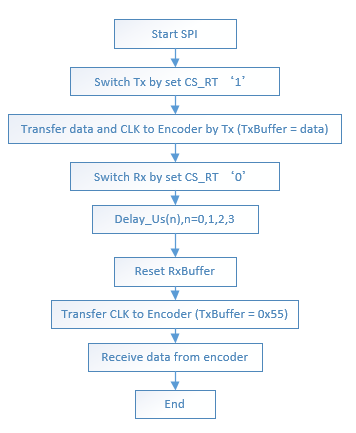
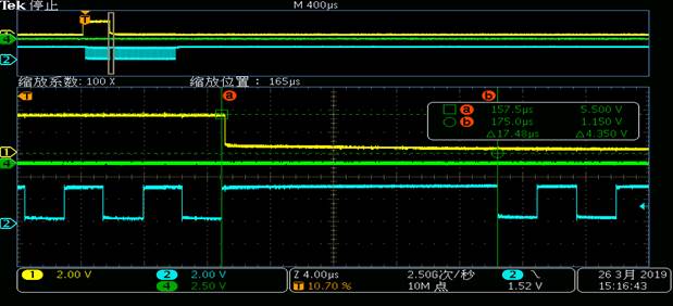
After filling the FIFO (for example, one word) to initiate a transmit, when can SPI CLK have the first pulse output? We found that, it was different in different baud rate.

The SPI is used to connect a slave device, which has strict delay request. 

Thanks a lot.

Br, Jordan

  • Jordan,

    Are you talking about "td(SPC)M Delay time, SPISTE active to SPICLK"? According to the DS, we have only min delay number. We don't have Max delay time.

    td(SPC)M is a function of tc(SPC)M (SPICLK cycle time). So, it is not surprising that td(SPC)M varies with baudrate.

    Regards,

    Manoj

  • Manoj,
    Is the delay fixed or varied between different transmit operation?
    We did a test like this:
    1) Delay 1~3 us
    2) Fill the FIFO, and initiate the transmit
    The total time of 1) and 2) are the same, like 12us, if the delay is between 1~3us. If it is over 4us, the time of 1) and 2) is about 17us.

    Br, Jordan
  • Jordan,

    Sorry, you probably need to clarify your question. I don't quite understand it. Are we talking about the same parameter I mentioned in my previous post.

    What delay time (1~3us) are you talking about?

    Regards,
    Manoj
  • Manoj,

    When n = 0/1/2/3,the result is the same. We'd like to know why.

    Here's the details. Or you can skip the first two pictures, and go to the third one, directly. 

    The connections of hardware are as follows:

    P1 is the SPI module,P2 is a chip that can select which one between Tx and Rx can connect to Data+ and Data- by CS_RT, P3 is encoder.

    In our program, first we need transfer an order of get position to encoder, and then Receive position data by transfer CLK to encoder. Because the P1 is master and P3 is slave, the CLK is always produced by SPI.

    We used FiFO mode.

            The sequences of operation are as follows:

            The data in encoder is only existed for a few time, so we want to know how long time(as time Tn) it is between we write 0x55 to TxBuffer and the first clock signal produces.

            Then, we find that the Delay_Us(n) is no effect when n = 0/1/2/3, the Tn is a const value, only when n=4,Tn is changed. The SPI Baud rate is 200KHz.

            We are puzzled about that, here is our test result:

            When n = 0/1/2/3,the result is the same. Why?

    When n = 4, the result is different with n = 0/1/2/3

    Br, Jordan

  • Jordan,

    Questions from my side fron your last post:-

    1) Are we talking about “td(SPC)M Delay time, SPISTE active to SPICLK” parameter is datasheet?

    2) Is CS_RT same as SPISTE signal? I guess you are using GPIO as SPISTE signal instead of HW SPISTE signal. Am I correct? If so, “td(SPC)M Delay time, SPISTE active to SPICLK” doesn't apply here. This timing applies only when you are using HW SPISTE signal.

    3) Does yellow proble line correspond to CS_RT signal?

    Regards,
    Manoj
  • Manoj,
    1) NO, it’s clear about the Td(SPC)M delay time. Now, the question is about the Library function ‘Delay_US(n)’. As we can see in picture 2, ‘Delay_US(n)’ can delay time about n us, but when used it before transmitting a data by SPI, we found that this not work normally. Because of the special time requirements, we need the time between CS_RT turn to low and the first clock produce. We used Dealy_US(n) to ensure CS_RT turning low, then we found an issue that can not understand. When n = 0/1/2/3, the time of delay is the same length, and when n = 4, the time increases a lot, the result are in picture 3 and picture 4.
    2)NO, CS_RT is a GPIO that we used to control a chip of switching SPI data transmitting direction. When CS_RT is low, data transmits from encoder to DSP, when CS_RT is high, data transmits from DSP to encoder. The chip of switching is not in DSP.
    3)Yes, yellow probe line is CS_RT signal.

    Br, Jordan
  • Jorda,

    Thanks for the clarification. Since you're using GPIO as SPISTE signal, datasheet parameter td(SPC)M Delay time, SPISTE active to SPICLK” doesn't apply here as mentioned in my previous post.

    Regarding your question on delay function, it is difficult for me to comment without knowing how you have configured your SPI peripheral routine. I don't think the problem is with delay routine. It is probably how you have configured SPI RX function after the delay function which is causing this behavior.

    Regards,
    Manoj