Part Number: TMS320F280049
Other Parts Discussed in Thread: C2000WARE
Tool/software: Code Composer Studio
Hello,
I want to set up a SCI connection with a custom board powered by TMS320F280049 in the 64pin package.
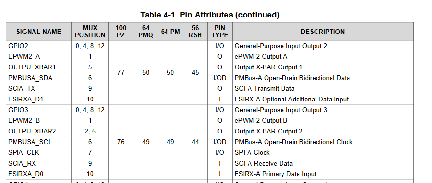
I tried to set up SCIA on GPIO2 and GPIO3, but I always get an error while uploading the code to the Microcontroller.
My code is basically the SCI Example Code from C2000Ware, but I changed the Part where the GPIO Settings are made.
The error occures when im trying to write to the GPAMUX1 registers (Line 29 and 33). If I delete this lines, there is no problem uploading the code.
void main(void)
{
    uint16_t ReceivedChar;
    unsigned char *msg;

    //
    // Initialize device clock and peripherals
    //
    InitSysCtrl();

    //
    // Initialize GPIO
    //
    InitGpio();

    //
    // For this example, only init the pins for the SCI-A port.
    // GPIO_SetupPinMux() - Sets the GPxMUX1/2 and GPyMUX1/2 register bits
    // GPIO_SetupPinOptions() - Sets the direction and configuration of GPIOs
    // These functions are found in the F28X7x_Gpio.c file.
    //

    EALLOW;

    GpioCtrlRegs.GPAMUX1.all = 0x00;

    GpioCtrlRegs.GPAPUD.bit.GPIO2 = 0;   // Enable pullup on GPIO2

    GpioCtrlRegs.GPAMUX1.bit.GPIO2 = 0x9;  // GPIO2 = SCITXDA

    GpioCtrlRegs.GPAPUD.bit.GPIO3 = 0;   // Enable pullup on GPIO3
    GpioCtrlRegs.GPAQSEL1.bit.GPIO3 = 3; // Asynch input
    GpioCtrlRegs.GPAMUX1.bit.GPIO3 = 0x9;  // GPIO3 = SCIRXDA


    EDIS;
    //
    // Disable CPU interrupts
    //
    DINT;

    //
    // Initialize the PIE control registers to their default state.
    // The default state is all PIE interrupts disabled and flags
    // are cleared.
    //
    InitPieCtrl();

    //
    // Disable CPU interrupts and clear all CPU interrupt flags
    //
    IER = 0x0000;
    IFR = 0x0000;

    //
    // Initialize the PIE vector table with pointers to the shell Interrupt
    // Service Routines (ISR)
    //
    InitPieVectTable();

    loopCounter = 0;

    initSCIAFIFO();                         // Initialize the SCI FIFO
    initSCIAEchoback();                     // Initialize SCI for echoback

    msg = "\r\n\n\nHello World!\0";
    transmitSCIAMessage(msg);

    msg = "\r\nYou will enter a character, and the DSP will echo it back! \n\0";
    transmitSCIAMessage(msg);

    for(;;)
    {
        msg = "\r\nEnter a character: \0";
        transmitSCIAMessage(msg);

        //
        // Wait for character
        //
        while(SciaRegs.SCIFFRX.bit.RXFFST == 0)
        {

        } // wait for empty state

        //
        // Get character
        //
        ReceivedChar = SciaRegs.SCIRXBUF.all;

        //
        // Echo character back
        //
        msg = "  You sent: \0";
        transmitSCIAMessage(msg);
        transmitSCIAChar(ReceivedChar);

        loopCounter++;
    }
}
This is the error:
C28xx_CPU1: Error: (Error -1135 @ 0x0) The debug probe reported an error. Confirm debug probe configuration and connections, reset the debug probe, and retry the operation. (Emulation package 8.0.903.2)
C28xx_CPU1: Trouble Halting Target CPU: (Error -1044 @ 0x0) The debug probe reported an error. Confirm debug probe configuration and connections, reset the debug probe, and retry the operation. (Emulation package 8.0.903.2)
C28xx_CPU1: Error: (Error -1135 @ 0x0) The debug probe reported an error. Confirm debug probe configuration and connections, reset the debug probe, and retry the operation. (Emulation package 8.0.903.2)
C28xx_CPU1: Unable to determine target status after 20 attempts
C28xx_CPU1: Failed to remove the debug state from the target before disconnecting. There may still be breakpoint op-codes embedded in program memory. It is recommended that you reset the emulator before you connect and reload your program before you continue debugging
Thanks in advance Sebastian