This thread has been locked.

If you have a related question, please click the "Ask a related question" button in the top right corner. The newly created question will be automatically linked to this question.

TMS320F28379D: No communication between MPU6050 and F28379d (launchpad)

Part Number: TMS320F28379D
Other Parts Discussed in Thread: C2000WARE

Hello,

I need help, advice.. with I2C on F28379d.

I would like port code from ATMEGA to the F28379 but MPU6050 breakboard don't send ACK when it receive his address

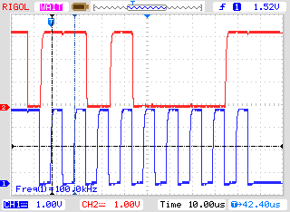
Electricaly, evrything is OK (of course, the MPU6050 breakboard is working, I check with an ATMEGA64)

I wrote my code from the C2000Ware example (I remove interruption)

Hereafter my code, I reduce it to the minimum!

//
// Included Files
//
#include "driverlib.h"
#include "device.h"

//
// Defines
//
#define SLAVE_ADDRESS               0x68

// Function Prototypes
void initI2C(void);

void main(void)
{

    // Initialize device clock and peripherals
    Device_init();

    // Disable pin locks and enable internal pullups.
    Device_initGPIO();

    // Initialize GPIOs 105 SCL A and 104 SDA A
    GPIO_setPinConfig(GPIO_104_SDAA);
    GPIO_setPadConfig(104, GPIO_PIN_TYPE_PULLUP);
    GPIO_setQualificationMode(104, GPIO_QUAL_ASYNC);

    GPIO_setPinConfig(GPIO_105_SCLA);
    GPIO_setPadConfig(105, GPIO_PIN_TYPE_PULLUP);
    GPIO_setQualificationMode(105, GPIO_QUAL_ASYNC);

    initI2C();

    while(1)
    {
        HWREGH(I2CA_BASE + I2C_O_SAR) = SLAVE_ADDRESS;

        HWREGH(I2CA_BASE + I2C_O_CNT) = 2;
        HWREGH(I2CA_BASE + I2C_O_DXR) = 0xAA; //for test
        HWREGH(I2CA_BASE + I2C_O_DXR) = 0x55; //

        HWREGH(I2CA_BASE + I2C_O_MDR) = 0x2E20;
        while (((HWREGH(I2CA_BASE + I2C_O_STR) & I2C_STR_ARDY) == I2C_STR_ARDY) == 0);
    }
}


//
// initI2C - Function to configure I2C A in FIFO mode.
//
void initI2C()
{

    // Must put I2C into reset before configuring it
    I2C_disableModule(I2CA_BASE);


    // I2C configuration. Use a 100kHz I2CCLK with a 50% duty cycle.
    I2C_initMaster(I2CA_BASE, DEVICE_SYSCLK_FREQ, 100000, I2C_DUTYCYCLE_50);
    I2C_setBitCount(I2CA_BASE, I2C_BITCOUNT_8);
    I2C_setSlaveAddress(I2CA_BASE, SLAVE_ADDRESS);
    I2C_setEmulationMode(I2CA_BASE, I2C_EMULATION_FREE_RUN);


    // FIFO configuration
    I2C_enableFIFO(I2CA_BASE);

    // Configuration complete. Enable the module.
    I2C_enableModule(I2CA_BASE);
}

I don't understand where can be the problem!

Thanks for answers

  • Hi,

    I briefly looked into your code. I don't see much issues with your code. Make sure your slave address is indeed correct.

    Regards,
    Manoj
  • Hi guillaumeI ,

    I encounter a lot of problem with 28379D and MPU9150 just like you. But I make it works recently. Here's my code write in bitfield.

    //###########################################################################
    //
    // FILE:    main.c
    //
    //###########################################################################
    
    // Included Files
    #include "F28x_Project.h"
    
    // defines
    #define Slave_Addr      0x0068
    #define DataNum         14
    #define RawNum          DataNum/2
    
    //MPU-9150 table
    #define ACCEL_XOUT_H     0x3B  //acceleration X 16-8 bits address
    
    //functions
    void i2c_a_init(void);
    void i2c_a_gpio_init(void);
    Uint16 i2c_a_read_data(Uint16);
    void i2c_a_write_data(Uint16,Uint16);
    Uint16 MPU_init(void);
    void Get_RawData(void);
    
    //Global Variables
    Uint16 DeviceID = 0;
    Uint16 DataBuffer[DataNum];
    Uint16 RawData[RawNum];
    Uint16 Ax,Ay,Az,Gx,Gy,Gz,Temp;


    void main (void)
    {
        /*
         * Initialize System Control:
         * PLL, WatchDog, enable Peripheral Clocks
         * This example function is found in the F2837xS_SysCtrl.c file.
         */
        InitSysCtrl();
    
        // Initialize GPIO:
        InitGpio();
    
        // Setting I2C pin
        i2c_a_gpio_init();
    
        /*
         * Clear all interrupts and initialize PIE vector table:
         * Disable CPU interrupts
         */
        DINT;
    
        /*
         * Initialize the PIE control registers to their default state.
         * The default state is all PIE interrupts disabled and flags
         * are cleared.
         * This function is found in the F2837xS_PieCtrl.c file.
         */
        InitPieCtrl();
    
        // Disable CPU interrupts and clear all CPU interrupt flags:
        IER = 0x0000;
        IFR = 0x0000;
    
        /*
         * Initialize the PIE vector table with pointers to the shell Interrupt
         * Service Routines (ISR).
         * This will populate the entire table, even if the interrupt
         * is not used in this example.  This is useful for debug purposes.
         * The shell ISR routines are found in F2837xS_DefaultIsr.c.
         * This function is found in F2837xS_PieVect.c.
         */
        InitPieVectTable();
    
    
        // Initialize the Device Peripherals:
        i2c_a_init();
    
        // Enable global Interrupts and higher priority real-time debug events:
        EINT;
    
        while(MPU_init() != 1);  //Initialize MPU9150
        for(;;){
            Get_RawData();       // Get Acceleration x,y,z temp Gyro x,y,z
        }
    
    
    }
    
    void i2c_a_init (void)
    {
        I2caRegs.I2CSAR.all = Slave_Addr;   // 7-bit Slave address - DS1672
    
        // Initialize I2C in master transmitter mode
        I2caRegs.I2CPSC.all = 19;           // I2C clock should be between 7Mhz-12Mhz  in this case 200MHz/(19+1) = 10MHz
        I2caRegs.I2CCLKL = 10;              // Prescale set for 400kHz bit rate
        I2caRegs.I2CCLKH = 5;
    
        I2caRegs.I2CIER.all = 0x24;         //enable interrupt of SCD and ARDY
    
        I2caRegs.I2CFFTX.all = 0x6000;      // Enable FIFO mode and TXFIFO
        I2caRegs.I2CFFRX.all = 0x2040;      // Enable RXFIFO, clear RXFFINT
    
        return;
    }
    
    void i2c_a_gpio_init (void)
    {
        EALLOW;
    
        // Set qualification for the selected I2C pins
        GpioCtrlRegs.GPDQSEL1.bit.GPIO104 = 3;
        GpioCtrlRegs.GPDQSEL1.bit.GPIO105 = 3;
        // Enable PULLUP
        GpioCtrlRegs.GPDPUD.bit.GPIO104 = 0;
        GpioCtrlRegs.GPDPUD.bit.GPIO105 = 0;
    
        EDIS;
    
        GPIO_SetupPinMux(104, GPIO_MUX_CPU1, 1);
        GPIO_SetupPinMux(105, GPIO_MUX_CPU1, 1);
    }
    
    Uint16 MPU_init(void)
    {
        Uint16 ID,a;
    
        ID = i2c_a_read_data(0x75);
    
        if(ID == 0x71){
            i2c_a_write_data(0x6B, 0x41);   // set MPU to sleep
            for(a=0;a<2000;a++){            //delay a little bit
            }
            i2c_a_write_data(0x6B, 0x01);   // Wake MPU up
            i2c_a_write_data(0x1B, 0x00);   // Accel Precision scale seclet ± 250 °/s
            i2c_a_write_data(0x1C, 0x00);   // Gyro Precision scale select ± 2g
            return 1;
        } else  return 0;
    
    }
    
    void fusion(void)
    {
        Uint16 a,b=0;
    
        for(a=0;a<7;a++){
            RawData[a] = (DataBuffer[b] << 8) + DataBuffer[b+1];
            b+=2;
        }
    
        Ax =   RawData[0];
        Ay =   RawData[1];
        Az =   RawData[2];
        Temp = RawData[3];
        Gx =   RawData[4];
        Gy =   RawData[5];
        Gz =   RawData[6];
    
    }
    
    void Get_RawData(void)
    {
        Uint16 i;
        Uint16 addr = ACCEL_XOUT_H;
    
        while (I2caRegs.I2CSTR.bit.BB == 1);        // busy loop (receive or send a start bit)
        I2caRegs.I2CSTR.bit.SCD = 1;                // Clear the SCD bit (stop condition bit)
        while(I2caRegs.I2CMDR.bit.STP == 1);        // make sure the i2c bus has stopped
        I2caRegs.I2CMDR.all = 0x2E20;               // STT=1, STP=1, MST=1, TRX=1, IRS=1
    
        I2caRegs.I2CCNT = 1;                        // send 1 byte
        I2caRegs.I2CDXR.all = addr;                 // send data to tx buffer
    
        while (I2caRegs.I2CMDR.bit.STP == 1);       // wait the last transmit complete
    
        I2caRegs.I2CMDR.all = 0x2C20;               // STT=1, STP=1, MST=1, TRX=0, IRS=1
    
        I2caRegs.I2CCNT = DataNum;
    
        while (I2caRegs.I2CSTR.bit.BB == 1);        // wait for MPU transmission complete (detect stop bit)
    
    
        for(i=0;i<=DataNum;i++){
            DataBuffer[i] = I2caRegs.I2CDRR.all;    // read data from buffer
        }
    
        fusion();                                   // fuse two 8it data to a 16 bit data which we want
    
    }
    
    Uint16 i2c_a_read_data (Uint16 register_address)
    {
        Uint16 temp;
    
        while (I2caRegs.I2CSTR.bit.BB == 1);        // busy loop (receive or send a start bit)
        I2caRegs.I2CSTR.bit.SCD = 1;                // Clear the SCD bit (stop condition bit)
        while(I2caRegs.I2CMDR.bit.STP == 1);        // Make sure I2C is not busy and has stopped
    
        I2caRegs.I2CMDR.all = 0x2E20;               // STT=1, STP=1, MST=1, TRX=1, IRS=1
    
        I2caRegs.I2CCNT = 1;                        // send 1 byte
        I2caRegs.I2CDXR.all = register_address;     // register adress
    
        while (I2caRegs.I2CMDR.bit.STP == 1);       // wait the last transmit complete
    
        I2caRegs.I2CMDR.all = 0x2C20;               // STT=1, STP=1, MST=1, TRX=0, IRS=1
    
        I2caRegs.I2CCNT = 1;                        // receive one byte
    
        while (I2caRegs.I2CSTR.bit.BB == 1);        // wait for MPU transmission complete (detect stop bit)
    
        temp = I2caRegs.I2CDRR.all;                 // read data from buffer
    
        return temp;                                // return data
    }
    
    void i2c_a_write_data (Uint16 register_address, Uint16 register_value)
    {
        while (I2caRegs.I2CSTR.bit.BB == 1);        // busy loop (receive or send a start bit)
        I2caRegs.I2CSTR.bit.SCD = 1;                // Clear the SCD bit (stop condition bit)
        while(I2caRegs.I2CMDR.bit.STP == 1);        // Make sure I2C is not busy and has stopped
    
        I2caRegs.I2CCNT = 2;                        // send 2 byte
    
    
        I2caRegs.I2CDXR.all = register_address;     // register address (1 byte)
        I2caRegs.I2CDXR.all = register_value;       // data to be sent (1 byte)
    
        I2caRegs.I2CMDR.all = 0x2E20;               // STT=1, STP=1, MST=1, TRX=1, IRS=1
    
        I2caRegs.I2CMDR.bit.STP = 1;                // stop bit when CNT=0
    
        while(I2caRegs.I2CSTR.bit.SCD != 1);        // wait for STOP condition
    
        return;
    }


    LapetusTTS

  • Thanks for your answer,

    I'm happy to not be the only one with difficulties on MPU

    I will try your code.

    Regards

  • Of course, I checked the breakboard and address: it works
    and according to the logic analizer this is the good value sent on the bus
  • Guillaumel,

    Have you already found a solution to your problem? If so, can you provide details on what fixed the issue?

    Regards,
    Manoj