This thread has been locked.

If you have a related question, please click the "Ask a related question" button in the top right corner. The newly created question will be automatically linked to this question.

TMS320F28035: high-precision EPWM TBPRD

Part Number: TMS320F28035


There are two H-bridges, the first arm is drived by CH1/CH2 and the second are is drived by CH3/CH4.The two H bridges is the same frequency, but the dead zone is different, and dead zone switch between the two arms.

As shown in the figure below, the front driver is CH1/CH2 with a dead time greater than CH3/CH4, and the second driver is CH3/CH4 with a dead time greater than CH1/CH2.

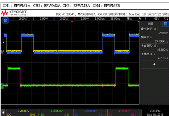
From the waveform diagram, the function has been realized, but there is such a problem in the debugging process.

During the debugging process, the following waveforms appear, that is, the first CH1/EPWM1A after switching has only half of the driving waveforms, and the subsequent waves are normal.

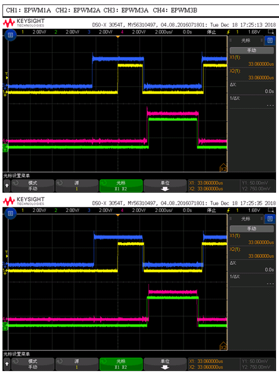
Try to analyze why EPWM1A appears this phenomenon, because the configuration of EPWM1A and EPWM3A is exactly the same, and the post-EPWM1A wave is also correct, so it is not clear why the first driver will appear half of the phenomenon.

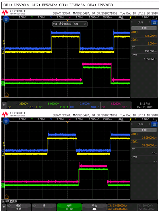
Finally, by modifying EPwm1Regs. HRPCTL. bit. HRPE = 1; EPwm1Regs. HRPCTL. bit. HRPE = 0; the following waveforms are obtained

1. At present, TMS320F28035PN is used.

2. Blockade and recovery are achieved through the configuration of register AQCTLA/AQCTLB, which is to configure AQCTLA/AQCTLB before each blockade or recovery.

We implement dead-zone switching under fixed-frequency open-loop. The two waves are calculated by the same loop, but the wave amount is fine-tuned according to the wave configuration after the wave is emitted. Take EPWM1A and EPWM3A as examples, both of them are EPwmRegs.AQCTLA.bit.CAD = AQ_SET; EPwmRegs.AQCTLA.bit.CAU = AQ_CLEAR; if the result of the loop calculation is CMP1, incremental. The dead time of EPWM 3A is CMP delta, which requires EPWM 1Regs. CMPA = CMP 1 - CMP delta, EPwm 3Regs. CMPA = CMP 1. Conversely, the dead time of EPWM 3A is larger than that of EPWM 1A, EPwm 1Regs. CMPA = CMP 1, EPwm 3Regs. CMPA = CMP delta.

3. At present, the phenomena tested are: under the configuration of EPwm1Regs. HRPCTL. bit. HRPE = 1, this phenomenon will occur every time when the first driver fixed after AQCTLA/AQCTLB is reconstructed, and the subsequent driving waveforms are normal.


The current configuration of EPWM1A's COMP loading mode is as follows: EPwm1Regs. CMPCTL. bit. LOADAMODE = CC_CTR_ZERO_PRD; EPwm1Regs. CMPCTL. bit. SHDWAMODE = CC_SHADOW;。


Combining with the above phenomena, I want to know why the first driver of EPWM1A will lose half when high-precision is enabled, and the shielding of high-precision EPWM1A will return to normal. What is the relationship between this, thank you.


  • Tobby,
    Are your pulses centered around ZRO or around PRD?

    e2e.ti.com/.../746906

    Regards,
    Cody
  • Cody Watkins

    Epwm1 is round by ZERO.

    When HRPWM, the shadow load mode is set to both CTR=ZERO AND PRD, the CMPx and CMPxHR shadow registers accessible by the user only get loaded at CTR=ZERO. This feature is only for Piccolo or all 28x?

    Even only get loader at CTR=ZERO when HRPWM, the drive should be:

    As do not configure any action when CTR=ZERO in program, I think with HR should lost first all drive not half drive .why this have a raise edge?

  • Tobby,

    Please center your pulses around CTR=PRD. I think this should make it work as you expected.

    The values that you set were updated on the first CTR=PRD in your figure. The problem is that in HRPWM mode the HR portion of the PMW's CMPA setting is only internally updated once per period. It is updated at CTR= ZRO, so you have the old setting up until CTR=0 and then the new setting after CTR=0.

    Regards,

    Cody 

  • Cody :

    Thanks for you reply.

    Please center your pulses around CTR=PRD. I think this should make it work as you expected.

    We have 2 channel 2H bridge ,the first channel is drive by EPWM1A/EPWM2A/EPWM3A/EPWM3B, as the describe above. The second channel is drive by EPWM4A/EPWM5A/EPWM6A/EPWM6B. The two channel have 90 degree phase shift by different pulses center, the EPWM4A is center around CTR=PRD and the second channel have no such half drive lost, so if we center EPWM1 pulse around CTR=PRD, the problem dissolve. But as the 90 degree phase shift, we can not change the center EPWM1 around CTR=PRD.

    The values that you set were updated on the first CTR=PRD in your figure. The problem is that in HRPWM mode the HR portion of the PMW's CMPA setting is only internally updated once per period. It is updated at CTR= ZRO, so you have the old setting up until CTR=0 and then the new setting after CTR=0.

    old setting up until CTR=0:(when drive low, this code execute every ZERO or PRD)

           ;EPWM1A, CAD = CLEAR, CAU = CLEAR

           MMOVXI      MR0,   #0x0050

        MMOV16      @_EPwm1Regs.AQCTLA.all,MR0

    new setting after CTR=0.(when drive recovery ,this code execute every ZERO or PRD)

           ;EPWM1A, CAD = SET, CAU = CLEAR

           MMOVXI      MR1,   #0x0090

        MMOV16      @_EPwm1Regs.AQCTLA.all,MR1

    According the setting either old or new ,when CTR= ZRO , epwm should have no action ,why this have a raise edge?

    Regards,

    Tobby


  • Tobby,

    please configure TBPHS for PWM3A/B to ensure the pulses are centered around CTR=ZRO.

    I believe that that CAD and CAU can be updated at anytime. It is only the CMPx and CMPxHR registers that only take affect at CTR=ZRO in HR mode.

    Therefore the rising edge occurs at zero because you reconfigured the CAD action to be set high, and the CMPA write has not yet taken place.

    Regards,
    Cody