This thread has been locked.

If you have a related question, please click the "Ask a related question" button in the top right corner. The newly created question will be automatically linked to this question.

TMS320F28335: strange output in CAN bus transmit loop

Part Number: TMS320F28335
Hi,
In our company, we have a custom board with TMS320F28335 module. Our software project is based on Example_2833xECap_apwm source code with addition of CAN bus transceiver (NXP TJA1043).
I have found an example project that is compatible with our hardware, it is named CAN_TXLOOP_A . The project is successfully compiled and run in RAM.
I am also using PCAN-USB Pro adapter to create a CAN network.
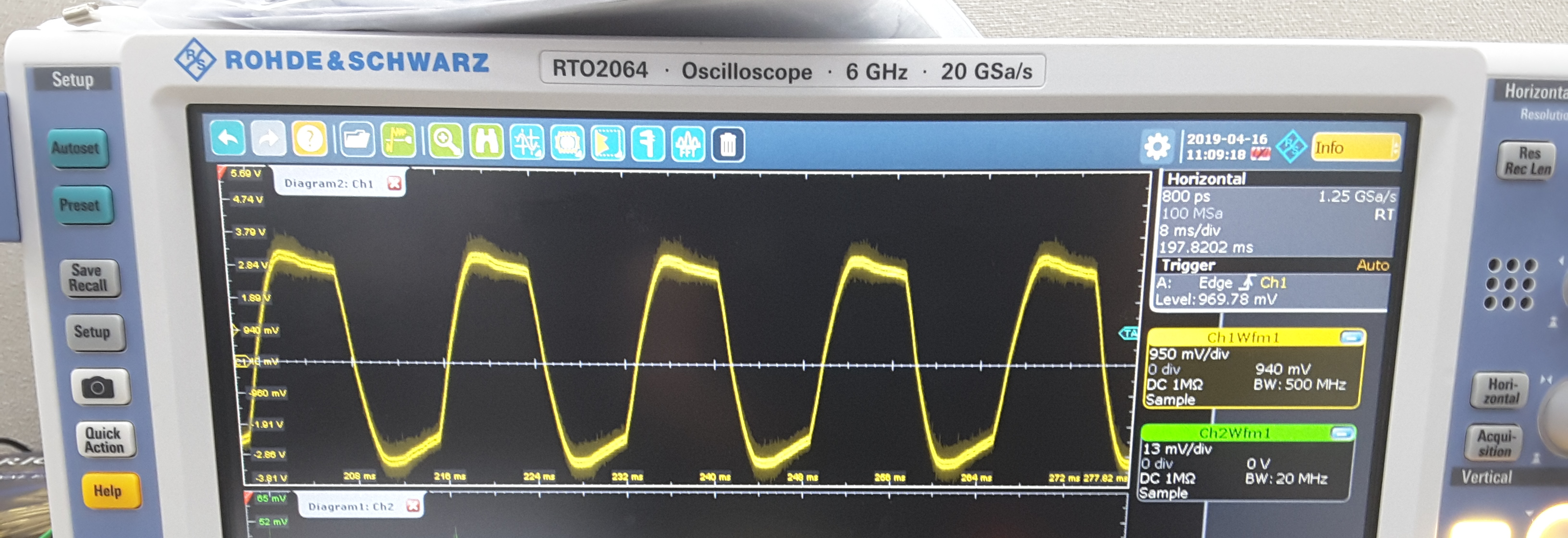
We are connecting an oscilloscope to check an output signal for CAN_HI signal. Unfortunately the signal does not look like a CAN bus message transmission. A photo is attached here. The PCAN adapter does recognize it as a CAN message and does not receive anything.
Any of your help will be very appreciated. 
Best Regards,
Vladimir Skvortsov
  • Vladimir,

                I presume you downloaded SPRA876 and compiled the transmit example CAN_TXLOOP_A. First, please compile and run this example “as is” , without integrating it with your project. It is a tested example and should work “as is” provided your input clock is 30 MHz. Have you looked at the Debug tips I provided in SPRA876? 

    I presume your scope is capable of triggering on CAN bus signals. Did you configure the bit-rate correctly on the scope?Have you tried triggering on CANTX pin of the DSP? If the scope does not decode the waveform, make sure input threshold value for the channel is correct. This is similar to the “trigger level” that is normally used for signals. 

    Your scope readout says 8ms/div. What you are seeing is definitely not a CAN signal. If the waveform acquisition is proper, you should see something similar to the below: (note that a different MSGID & data are transmitted below, compared to what example you are using does)


  • Hi Hareesh,

    Thank you very much for your quick response.

    Hareesh J said:

    Vladimir,

                I presume you downloaded SPRA876 and compiled the transmit example CAN_TXLOOP_A. First, please compile and run this example “as is” , without integrating it with your project. It is a tested example and should work “as is” provided your input clock is 30 MHz. Have you looked at the Debug tips I provided in SPRA876? 

    After getting your response, we successfully compiled and run a project based on CAN_TXLOOP_A example only. What do you mean saying “input clock is 30 MHz”? Do you mean a CAN clock? Our DSP chip is TMSF28335, so it works on 150 MHz CPU clock and CAN clock is 75 MHz. Yes, we looked at SPRA876 document and use it as one of important references.

    I presume your scope is capable of triggering on CAN bus signals. Did you configure the bit-rate correctly on the scope?Have you tried triggering on CANTX pin of the DSP? If the scope does not decode the waveform, make sure input threshold value for the channel is correct. This is similar to the “trigger level” that is normally used for signals. 

    Our oscilloscope has no special CAN bus capability. We have 2 extra CAN to USB interface devices: (1) Vector VN1630A, (2) Peak PCAN USB Pro. Both we used to test our oscilloscope CAN signal capabilities. We just transmitted in loop the same CAN messages and we got pictures (below) that are very similar to your attached oscilloscope screenshot. From these tests we can make conclusion that our oscilloscope is capable to display a proper CAN signal.

    Vector VN 1630A Peak PCAN USB Pro

    > Also we connected an oscilloscope probe to CANTXA (GPIO31) pin on our TMS320F28335 module (the module is soldered by local company, link: http://syncworks.co.kr/shop/goods/goods_view.php?&goodsno=200902378&category=), running the TX_LOOP_A application, and we finally got the following picture which is similar to our previous we got from transceiver CAN_HI signal.


    Unfortunately, it does not look like a CAN signal as well.


    Your scope readout says 8ms/div. What you are seeing is definitely not a CAN signal. If the waveform acquisition is proper, you should see something similar to the below: (note that a different MSGID & data are transmitted below, compared to what example you are using does)


    Thank you for sending the oscilloscope screenshot.

    So we are still having a problem.

    Best regards,

    Vladimir

  • After getting your response, we successfully compiled and run a project based on CAN_TXLOOP_A example only. What do you mean saying “input clock is 30 MHz”? Do you mean a CAN clock? Our DSP chip is TMSF28335, so it works on 150 MHz CPU clock and CAN clock is 75 MHz. Yes, we looked at SPRA876 document and use it as one of important references.

    By input clock, I am referring to the clock input to the DSP, by way of either a crystal oscillator connected to X1/X2 pins or an external oscillator connected to XCLKIN pin.

    Our oscilloscope has no special CAN bus capability. We have 2 extra CAN to USB interface devices: (1) Vector VN1630A, (2) Peak PCAN USB Pro. Both we used to test our oscilloscope CAN signal capabilities. We just transmitted in loop the same CAN messages and we got pictures (below) that are very similar to your attached oscilloscope screenshot. From these tests we can make conclusion that our oscilloscope is capable to display a proper CAN signal.

    Agree. Having a CAN trigger capability makes it very easy to acquire/decode CAN waveforms, but you should be able to capture the activity on a scope without this capability as well.

    Would you be willing to privately share your schematics with me?
  • Closing the thread due to inactivity.