This thread has been locked.

If you have a related question, please click the "Ask a related question" button in the top right corner. The newly created question will be automatically linked to this question.

TMS320F28035: Noticed a SCI RX interrupt delay in F28035

Part Number: TMS320F28035
Other Parts Discussed in Thread: C2000WARE

Hi Champs,

Here is a question about the RX interrupt of SCI.

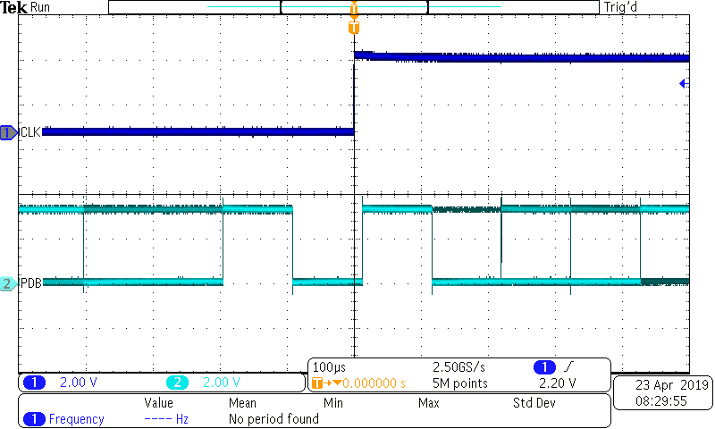
I am doing an experiment on controlcard based on Example_2803xSci_FFDLB_int. I connected TX and RX on card rather than using internal loopback to simulate the SCI communication between 2 MCUs. In the RX interrupt, I toggle a GPIO to indicate a interrupt. Here is what I observed:

As shown in the picture, after the stop bit, there is a 100us delay before the GPIO is toggled(9600 baud-rate). Is RX designed to be triggered one bit after the stop bit? I only used 1 stop bit. The similar result is also observed by my customer.The source code of RX isr is as below:

_interrupt void
sciaRxFifoIsr(void)
{
Uint16 i;
for(i=0;i<2;i++)
{
rdataA[i]=SciaRegs.SCIRXBUF.all; // Read data
}
for(i=0;i<2;i++) // Check received data
{
if(rdataA[i] != ( (rdata_pointA+1) & 0x00FF) )
{
// error();
}
}
rdata_pointA = (rdata_pointA+1) & 0x00FF;

SciaRegs.SCIFFRX.bit.RXFFOVRCLR=1; // Clear Overflow flag
SciaRegs.SCIFFRX.bit.RXFFINTCLR=1; // Clear Interrupt flag

PieCtrlRegs.PIEACK.all|=0x100; // Issue PIE ack
GpioDataRegs.GPATOGGLE.bit.GPIO0 =1;

}

  • Weiqi,

    There is a minimum latency for internal interrupts of 14 cycles (to enter the ISR), plus the code you have in the ISR before the GPIO pin gets toggled.

    I hope this helps. If this answers your question, please click the green "Verified Answer" button. Thanks.

    - Ken
  • Hi Ken,

    As you can see, there is a 100us delay. It seems like 14 cycles interrupt latency + ISR code will not consume 100us.

    I also did another test to run the SCI communication under 19200 baud rate:

    It it obvious that the latency time is related to baud rate rather than a fixed time period.

    Could you please review my question and provide a reasonable answer.

    Thanks,

    Brian

  • Brian,

    Could you please check if this problem is being caused by a synchronization issue, such as the next bit time after a stop bit? Also, could you please run this test on a "known-good" example from C2000Ware for a comparison?

    - Ken
  • This is the Example_2803xSci_FFDLB_int.

    The only thing I did is adding the GPIO toggle code in RX_ISR.
    My customer has also performed the same test on their prototype and get the same result.

    So here is our concern, according to the waveform, the RX_ISR only get triggered on-bit after the stop bit, where we move the data from FIFO into RAM. What if the reading data operation happens after the next start bit, will this cause a transfer error?

    The reason why we are asking this is we observed a transfer fault between MCU. Under 4800 baud rate the transmitting is successful, while for 9600 baud rate we observed a frame fault and nothing can be received.

    So we tested the SCI signal and noticed the result above. It does not seems like a configuration problem. Is the SCI RX ISR designed to be triggered a bit after the stop bit?

    Regards,
    Brian
  • Brian,

    Please try moving PieCtrlRegs.PIEACK.all|=0x100; to the beginning of the ISR. Let me know if this resolves the issue. Thanks.

    - Ken
  • Brian

    We were able to reproduce the results that you are experiencing and this will be send to the design team for confirmation. It appears that the interrupt is being synchronized to the next bit time after a stop bit. After being confirmed by the design team, the documentation will be updated accordingly. Thanks again for pointing this out to us.

    - Ken
  • Brian,

    I just want to share the comments and explanation from our design team:

    IN SCI module, each bit is sampled 8 times by the baud clock and decision to latch it internally is taken after majority voting, which is 7th clock sample as shown in the "SCI Asynchronous Communications Format" figure in the User's Guide/TRM. Hence as per design implementation, the RX_RDY gets generated after STOP bit detection in the next 7th clock sample.

    Thus after Stop bit, the interrupt will be triggered at (7 * BAUD_CLK_PERIOD)/8 + 3SYSCLK.

    Also, note that in the "SCI RX Signals in Communication Modes" figure in the User's Guide/TRM - the RXRDY asserts after STOP bit which is not matching with the figure (waveform) and need to be updated.

    I hope this helps in addressing your issue.

    - Ken