Other Parts Discussed in Thread: CONTROLSUITE
Tool/software: Code Composer Studio
Dear TI members,
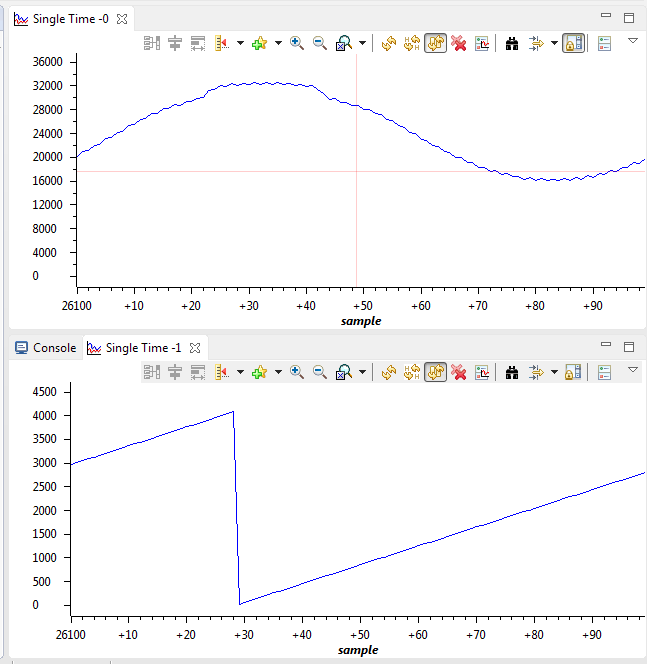
I am trying to implement a single phase PLL to determine the phase of an ac signal. I have managed to make my system measure an AC signal, and output a phase (using CCSUITE 1ph_PLL template) however the output phase of the PLL has been moving up and down and sometimes displaying terrible transients as seen in the next figs:
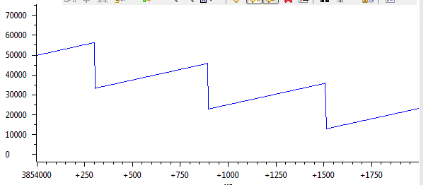

I also included an offset with the signal generator so that the ADC captures both positive and negative values
My ADC also displays wrong results at some values of my grid frequency (it works for 100Hz, 500Hz, 1000Hz), but it shows terrible results for 60Hz for example.
ISR:
interrupt void ADCINT1_ISR(void)
{
static Uint16 *AdcBufPtr1 = Va;				// Pointer to buffer - static so never lost
static Uint16 *AdcBufPtr2 = Vb;
//static Uint32 *AdcBufPtr3 = Vc;
static volatile Uint16 GPIO34_count = 0;		// Counter for pin toggle
static SPLL_1ph_IQ spll1;

	//ADC has 12 bits, values range from 0 to 4095

	PieCtrlRegs.PIEACK.all = PIEACK_GROUP1;		// Must acknowledge the PIE group

//--- Manage the ADC registers
	AdcRegs.ADCINTFLGCLR.bit.ADCINT1 = 1;		// Clear ADCINT1 flag

//--- Read the ADC result
	*AdcBufPtr1++ = 	AdcResult.ADCRESULT0;     	// Read the result

	spll1.AC_input =(long)(AdcResult.ADCRESULT0<<3);
	SPLL_1ph_IQ_FUNC(&spll1);

	//*AdcBufPtr2++ = 	AdcResult.ADCRESULT1;
	*AdcBufPtr2++ = 	spll1.theta[1];
	//*AdcBufPtr3++ = 	AdcResult.ADCRESULT2;

//--- Brute-force the circular buffers
	if( AdcBufPtr1 == (Va + ADC_BUF_LEN) )
	{
		AdcBufPtr1 = Va;						// Rewind the pointer to beginning
	}
	if( AdcBufPtr2 == (Vb + ADC_BUF_LEN) )
	{
		AdcBufPtr2 = Vb;						// Rewind the pointer to beginning
}
	if(DEBUG_TOGGLE == 1)
	{
		GpioDataRegs.GPATOGGLE.bit.GPIO18 = 1;		// Toggle the pin
	}

//--- Example: Toggle GPIO34 at a 0.5 sec rate (connected to the LED on the ControlSTICK).
//             (1/50000 sec/sample)*(1 samples/int)*(x interrupts/toggle) = (0.5 sec/toggle)
//             ==> x = 25000
	if(GPIO34_count++ > 25000)					// Toggle slowly to see the LED blink
	{
		GpioDataRegs.GPBTOGGLE.bit.GPIO34 = 1;	// Toggle the pin
		GPIO34_count = 0;						// Reset the counter
	}
}
}
MAIN:
#include "Lab.h"
	#include "SPLL_1ph_IQ.h"
	#include "Solar_IQ.h"
	#include "IQmathLib.h"

	#define GRID_FREQ    100
	#define PI 3.141592653589
	#define ISR_FREQUENCY 250000.0
	Uint16 DEBUG_TOGGLE = 1;					// Used for realtime mode investigation test

	Uint16 Va[ADC_BUF_LEN];
	Uint16 Vb[ADC_BUF_LEN];
	//Uint32 Vc[ADC_BUF_LEN];

	//DEFINE STRUCTS

	SPLL_1ph_IQ spll1;
	SPLL_1ph_IQ_NOTCH_COEFF spll_notch_coef1;

	void main(void) {


	//--- CPU Initialization

	InitSysCtrl();						// Initialize the CPU (FILE: SysCtrl.c)
	InitGpio();							// Initialize the shared GPIO pins (FILE: Gpio.c)
	InitPieCtrl();						// Initialize and enable the PIE (FILE: PieCtrl.c)
	InitWatchdog();						// Initialize the Watchdog Timer (FILE: WatchDog.c)

	//--- Peripheral Initialization
	InitAdc();							// Initialize the ADC (FILE: Adc.c)
	InitEPwm();							// Initialize the EPwm (FILE: EPwm.c)


	//--- Enable global interrupts
	asm(" CLRC INTM, DBGM");			// Enable global interrupts and realtime debug

	//PLL STARTS HERE
	// ------------- Software PLL for Grid Tie Applications ----------


	#define B0_LPF SPLL_Q(166.877556)
	#define B1_LPF SPLL_Q(-166.322444)
	#define A1_LPF SPLL_Q(-1.0)

	SPLL_1ph_IQ_init(GRID_FREQ,_IQ21((long)(1.0/ISR_FREQUENCY)),&spll1);
	SPLL_1ph_IQ_notch_coeff_update(((long)(1.0/ISR_FREQUENCY)),(long)(2*PI*ISR_FREQUENCY*2),(long)0.00001,(long)0.1,&spll1);

	//--- Main Loop
	while(1)							// endless loop - wait for an interrupt
	{
		asm(" NOP"); //program works only with interruptions ISR

	}
}
PLL (FROM controlSUITE):
#ifndef SPLL_1ph_IQ_H_
#define SPLL_1ph_IQ_H_

#define SPLL_Q _IQ21
#define SPLL_Qmpy _IQ21mpy

//*********** Structure Definition ********//
typedef struct{
	int32	B2_notch;
	int32	B1_notch;
	int32	B0_notch;
	int32	A2_notch;
	int32	A1_notch;
}SPLL_1ph_IQ_NOTCH_COEFF;

typedef struct{
	int32	B1_lf;
	int32	B0_lf;
	int32	A1_lf;
}SPLL_1ph_IQ_LPF_COEFF;

typedef struct{
	int32	AC_input;
	int32	theta[2];
	int32	cos[2];
	int32	sin[2];
	int32	wo;
	int32	wn;

	SPLL_1ph_IQ_NOTCH_COEFF notch_coeff;
	SPLL_1ph_IQ_LPF_COEFF	lpf_coeff;

	int32	Upd[3];
	int32	ynotch[3];
	int32	ylf[2];
	int32	delta_t;
}SPLL_1ph_IQ;

//*********** Function Declarations *******//
void SPLL_1ph_IQ_init(int Grid_freq, long DELTA_T, SPLL_1ph_IQ *spll);
void SPLL_1ph_IQ_notch_coeff_update(long delta_T, long wn,long c2, long c1, SPLL_1ph_IQ *spll_obj);
void SPLL_1ph_IQ_FUNC(SPLL_1ph_IQ *spll1);

//*********** Macro Definition ***********//
#define SPLL_1ph_IQ_MACRO(v)						 																																															\
	/* Phase Detect*/								 																																															\
	v.Upd[0]=SPLL_Qmpy(v.AC_input,v.cos[1]);		 																																															\
	/* Notch Filter*/								 																																															\
	v.ynotch[0]=-SPLL_Qmpy(v.notch_coeff.A1_notch,v.ynotch[1])-SPLL_Qmpy(v.notch_coeff.A2_notch,v.ynotch[2])+SPLL_Qmpy(v.notch_coeff.B0_notch,v.Upd[0])+SPLL_Qmpy(v.notch_coeff.B1_notch,v.Upd[1])+SPLL_Qmpy(v.notch_coeff.B2_notch,v.Upd[2]);	\
	/* Update Upd Array for future use*/			 																																															\
	v.Upd[2]=v.Upd[1];								 																																															\
	v.Upd[1]=v.Upd[0];								 																																															\
	/* LPF*/										 																																															\
	v.ylf[0]=-SPLL_Qmpy(v.lpf_coeff.A1_lf,v.ylf[1])+SPLL_Qmpy(v.lpf_coeff.B0_lf,v.ynotch[0])+SPLL_Qmpy(v.lpf_coeff.B1_lf,v.ynotch[1]);																											\
	/* Update Array for future use*/				 																																															\
	v.ynotch[2]=v.ynotch[1];						 																																															\
	v.ynotch[1]=v.ynotch[0];						 																																															\
	v.ylf[1]=v.ylf[0];								 																																															\
	/*VCO*/											 																																															\
	v.wo=v.wn+v.ylf[0];								 																																															\
	/* integration process */						 																																															\
	v.sin[0]=v.sin[1]+SPLL_Qmpy((SPLL_Qmpy(v.delta_t,v.wo)),v.cos[1]);																																											\
	v.cos[0]=v.cos[1]-SPLL_Qmpy((SPLL_Qmpy(v.delta_t,v.wo)),v.sin[1]);																																											\
	if(v.sin[0]>SPLL_Q(0.99))						 																																															\
		v.sin[0]=SPLL_Q(0.99);						 																																															\
	else if(v.sin[0]<SPLL_Q(-0.99))					 																																															\
		v.sin[0]=SPLL_Q(-0.99);						 																																															\
	if(v.cos[0]>SPLL_Q(0.99))						 																																															\
		v.cos[0]=SPLL_Q(0.99);						 																																															\
	else if(v.cos[0]<SPLL_Q(-0.99))					 																																															\
		v.cos[0]=SPLL_Q(-0.99);						 																																															\
	v.theta[0]=v.theta[1]+SPLL_Qmpy(SPLL_Qmpy(v.wo,SPLL_Q(0.159154943)),v.delta_t);																																								\
	if(v.sin[0]>SPLL_Q(0.0) && v.sin[1]<=SPLL_Q(0.0))					 																																										\
	{																	 																																										\
		v.theta[0]=SPLL_Q(0.0);											 																																										\
	}																	 																																										\
	v.theta[1]=v.theta[0];												 																																										\
	v.sin[1]=v.sin[0];													 																																										\
	v.cos[1]=v.cos[0];													 																																										\


#endif /* SPLL_1ph_IQ_H_ */
I suspect the following (but I am not sure how to address it)
1- I need to insert the offset to the signal inside the code instead of in the signal generator
2- I need to send a sinusoid signal with 0 offset to the PLL.
update -> I did that my subtracting the signal by its average, but I still get the same output phase
3- Also, I noticed that my graph function works for 100Hz when I have a buffer of size 500, but as I change the size of the buffer, the graph also changes, so I am thinking that maybe the system does work, but I will only see the right output at certain buffer sizes.
Any help/advice would be welcome.
Thank you,
Victor