This thread has been locked.

If you have a related question, please click the "Ask a related question" button in the top right corner. The newly created question will be automatically linked to this question.

TMS320F28379D: Maximum Baudrate

Part Number: TMS320F28379D
Other Parts Discussed in Thread: PROFIBUS

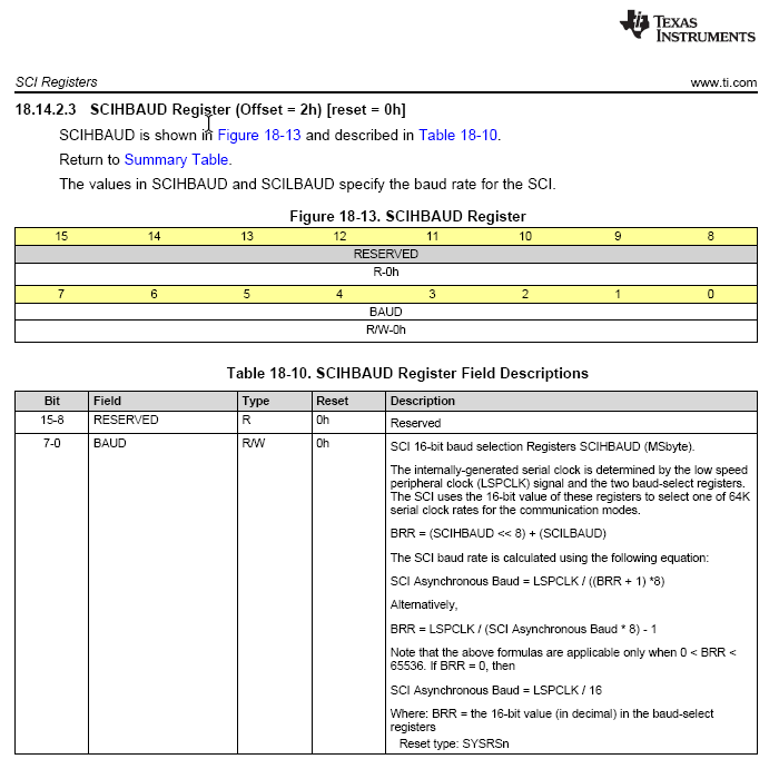
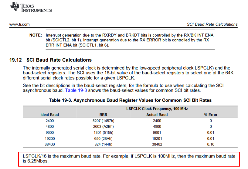
The TRM (and the code of sci.c from C200ware) says, the maximum baudrate ist LSPCLK / 16.

But I experienced the max baudrate is only LSPCLK / 32.

My LSPCLK is 200 MHz.

SCI is still working with 6.25 MBit/s (=200MHz / 8 / 4 with BRR = 3 => divider =4).

When BRR is set below 3 (e.g. 2) the SCI does not work anymore. No signal comes out of TX.

Why?

SCI shall work down to divider = 0 and then with Baudrate = LSPCLK / 16.

Please any solution. I want to implement a Profibus like 12 MBit link.

  • Dirk,

    I was wondering if you are using the F28379D LaunchPad with the header file example code? If so, then please note that when using the peripheral register header files with the LaunchPad, in \f2837xd\common\include\device.h there is a #ifdef preprocessor directive for _LAUNCHXL_F28379D. You will need to setup this predefined symbols in your project properties.

    Under “C2000 Compiler” select “Advanced Options” and then “Predefined Symbols”. In the predefined name box (“Pre-define NAME”) click the Add icon (first icon with green plus sign). Then in the “Enter Value” window type _LAUNCHXL_F28379D (note leading underscore). Click OK to include each name. This names are used in the project to conditionally include the peripheral register header files code specific to the LaunchPad. Finally, click OK to save and close the Properties window.

    This will affect the device clocking, which will affect the baud rate.

    I hope this helps. If this answers your question, please click the green "Verified Answer" button. Thanks.

    - Ken
  • Of couse I already have set this define, it was automatically set when using the example project.

    And I changed the settings for LSPCLK to 200 MHz and I double checked LSPCLK is really 200 MHz (and not 50 MHz like it was configured in the example code).

    After measurements I'm save to say LSPCLK is in reality 200 MHz and I also checked the BRR divider calculated in sci.c. Everything is perfect and LSPCLK, the calculated divider and the resulting baudrate matches and everything works with resulting baudrates up to 6.25 MHz. But above 6.25 MHz the sci tx-pin is dead.

  • Dirk,

    Please see this related post:

    e2e.ti.com/.../280552

    I hope this helps. If this answers your question, please click the green "Verified Answer" button. Thanks.

    - Ken
  • Hallo Ken,

    thank you very much for your help!

    That is the reason. The GPIO-Pin attached to the SCI can not exceed 10 MHz, even the SCI can work with 12.5 MHz. So the SCI is working internally with 12.5MHz but the signals are not sended out.

    I changed the SYSCLK from 200 MHz to 160 MHz to reach the 10 MHz (160 MHz / BRR = 16) and the SCI is still sending signals with 10 MHz.

    Even this is no solution for me, I understand now what is going on.

    Thanks, Dirk

  • After I was able to use the SCI with 10 MHz and I'm save to say my clocks are properly set, I searched the TRM and the datasheet.

    The max GPIO toggle frequency shall be 25 MHz. So 12.5 MHz SCI rate shall be reached.

    The SCI rate shall be able to reach 50 MHz according to TRM.

    So it is still unclear, why the SCI stops working above 10 MHz.

  • Dirk,

    Please note that your screen capture is for SPI and not SCI. I will need to check this bullet with our SPI expert for comment.

    - Ken
  • Oh, I'm sorry. You are right.
    I just jumped one chapter to far and hit the SPI chapter (5.12.5) instead the SCI (5.12.4).
    But I'm really talking about the SCI.
    It stops working above 10 MHz but I think It shall work at 12.5 MHz.
  • Dirk,

    Please see the TRM section 19.12. Could you let me know if you are using the internal oscillator or external clock?

    - Ken
  • Hallo Ken,

    I'm using the external clock with 10 MHz. It is multiplied with 40 and divided with 2 => 10 MHz * 40 / 20 => 200 MHz.

    LSPCLK is also 200 MHz, because the divider is set to 1. I did measure this.

    Regarding to chapter 19.12 the max baudrate of 12.5 MHz shall be reached, but only 10 MHz are working. Above 10 MHz no pin toggle on SCI TX can be observed.

    Regards   Dirk

  • Dirk,

    The reason I asked about your clock source is because if using INTOSC1 or INTOSC2 as the clock source, then the maximum frequency is 194 MHz. Please try using LSPCLK as 100 MHz.

    - Ken
  • Hallo Ken,

    with LSPCLK = 100 MHz and LSPCLK/16 is the maximum baud rate, never more than 6.25 MHz could be reached (100 MHz / 16 = 6.25 MHz).
    There is nothing to try.

    Regards Dirk
  • Dirk,

    We ran a test and we were able to achieve 12.5 MHz using the following setting below.  Do these setting match with what you are using?  Please note that the oscilloscope image at the bottom is using SCI-A on the F28379D LaunchPad.  The signal does not look very good since it was probed on the board without a good ground connection and using 32 AWG wire.

    changing SCILBAUD to 1, the same 12.5MHz was achieved:

    I hope this helps. If this answers your question, please click the green "Verified Answer" button. Thanks.

    - Ken

  • Hallo Ken,

    thank you very much for your effort and for detailed reproducing that the SCI is working with 12.5 MHz.

    The failure must be clearly on my side. I'm still trying to figure out what is going on my installation and what I did wrong.

    Thanks a lot.

    Regards  Dirk

  • Dirk,,

    F28379D SPI does support High-speed mode on certain GPIO pins. The GPIO pins which supports high-speed mode is documented in

    Pg: 928, Table 8-6 GPIO Configuration for High-Speed SPI

    Regards,

    Manoj