


Part Number: TMS320F28379D
Other Parts Discussed in Thread: LAUNCHXL-F28379D
Dear all,
As the title may suggest, I am working with TI’s heavy weapon, the TMS320F28379D (PTP package, that one with 176 terminals), in a custom board. The application will be power control (more specifically, motor control), with a DC bus voltage of 900V. Therefore, there will be an isolation between the board and the programmer/debugger. I stole inspired myself on TI’s LAUNCHXL-F28379D design and I intend to use both isolation ICs (ISO7231 and ISO7240) in the same manner as the Launchpad. But instead of having another microcontroller as programmer/debugger, I will have a XDS110 Debug Probe doing this job. The idea is to have less components on the board and rely on a high-quality product instead of risking making my own stuff.
However, I have some questions regarding the circuit for this configuration. Can anyone help me?
The microcontroller’s datasheet (document SPRS880K) indicate, on section 5.9.5, how to connect the JTAG with the microcontroller, as seen below. I will consider only the 20-pin design, since the XDS110 have this connector:
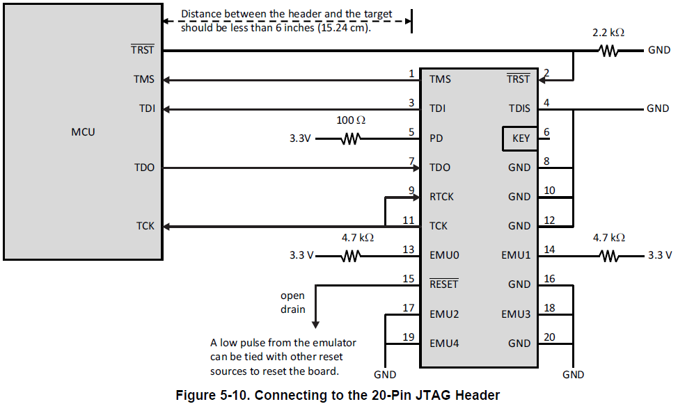
However, it shows only a direct connection between the JTAG and the microcontroller, and it does not consider an isolation between them. My custom board will have something like this:

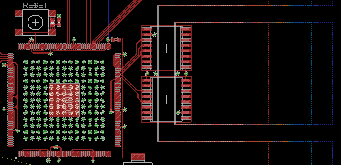
(Note: it is still being designed, thus many components – like capacitors for the MCU supply pins – are missing)
Based on this, I would like to ask some questions. A couple of them are kinda basic, and I think I know the answer, but I would like to make sure. It is somehow easy to fix a code, but wrong connections between SMD components in a compact and heavily populated PCB can be painful…
1 – Is the XDS110 enough to program and begug the TMS320F28379D? Will I be missing any funcionality as compared to the LAUNCHXL-F28379D?
2 – In my design, an USB communication is not needed. Thus, pins 130 and 131 (described as “USB PHY differential data” and assigned as “USB0DM” and “USB0DP”, respectively) are not being used. In the LAUNCHXL-F28379D, this does not happen, and both pins have a connection to both isolation ICs, that connects to the programmer/debugger MCU. Can all the funcionalities (program and debug) of the XDS110 be used by only connecting it to pins TRSTn, TMS, TDI, TDO and TCK? I do have in mind their directions, and I am taking this into consideration when using the isolation ICs.
3 – The LAUNCHXL-F28379D have three switches, with purposes of selecting boot modes of the microcontroller. Do my design need anything similar, or just the five signals described on question 2 are enough?
4 – The TMS320F28379D datasheet shows some resistors being used to pull up and down a couple signals from the probe. Is it safe to assume that, in an isolated scenario, those resistors would be used in the same manner, and be placed only in the “isolated part” of my board (i.e. near the connectors for the XDS110)? Do I need any other pullup/pulldown resistor in the “non-isolated part” of my board (i.e. near the microcontroller)?
5 – According to the XDS110 Debug Probe User’s Guide (document SPRUI94), it seems that the XDS110 Probe have two connectors. A 20-pin header for the signals (labeled “DEBUG”) and a 14-pin “auxiliar function” header (labeled “AUX. FUNCTIONS”).
Can I assume that the MCU datasheet shows an example that can be considered the XDS110 (the signal names for the MCU datasheet and the XDS110 User’s Guide are very similar), and connect those signals in the same manner as the first picture?
In addition, for the auxiliar connector, can I use only four pins (two “TGTSUPPLYIN” and two “GND”) for supply purposes? Can I just leave all the other pins unnused (i.e. floating)? Since the microcontroller will not be supplied by the probe, I don’t think that all other signals would be useful in my situation.
6 – The XDS110 uses two headers, one 20-pin and one 14-pin, as mentioned before. It seems that their “official names” are CTI-20 (or Compact TI 20-pin) and CTI-14 (or Compact TI 14-pin). My goal is to solder the CTI-20 and CTI-14 male header connectors in my custom PCB (inside that “isolated rectangle” shown on the third picture – I will adjust its size if needed) to use the cables provided in the XDS110 package directly, without needing to use the adaptors (since they make a small connector big – and big connectors is exactly what I’m trying to avoid).
However, I am really having some trouble to find these connectors, both to buy and their EAGLE libraries (I am almost sure that I will have to make that one). By searching using different names, all I find is adaptors (that contain the male headers). Does anyone knows where can I buy only the CTI-20 and CTI-14 male headers? I would also like their detailed dimensions (pad size, spacing, etc.) to create a part to be used on my board.
That’s is for today! Thank you for your time.
Best regards,
Gabriel.

