Part Number: TMS320F28069M
Tool/software: Code Composer Studio
Hi all,
I've a strange problem with custom board mounting TMS320F28069M MCU. I try to program it with XDS110 (from Launchpad F280049C).
I tryed to create from scratch a new project using DEV USER GUIDE indications.
All work fine, compile ok. I've "test.out" binary ready to be loaded into MCU. I would use standard JTAG connection and made this schematic:

This is my "ccxml" configuration:
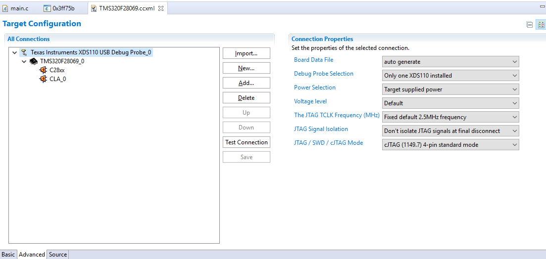
If i click "Test Connection" all seems to be fine:
[Start: Texas Instruments XDS110 USB Debug Probe_0]
Execute the command:
%ccs_base%/common/uscif/dbgjtag -f %boarddatafile% -rv -o -S integrity
[Result]
-----[Print the board config pathname(s)]------------------------------------
C:\Users\STUDIO~1\AppData\Local\TEXASI~1\
CCS\ti\0\0\BrdDat\testBoard.dat
-----[Print the reset-command software log-file]-----------------------------
This utility has selected a 100- or 510-class product.
This utility will load the adapter 'jioxds110.dll'.
The library build date was 'Apr 30 2019'.
The library build time was '14:17:18'.
The library package version is '8.1.0.00012'.
The library component version is '35.35.0.0'.
The controller does not use a programmable FPGA.
The controller has a version number of '5' (0x00000005).
The controller has an insertion length of '0' (0x00000000).
This utility will attempt to reset the controller.
This utility has successfully reset the controller.
-----[Print the reset-command hardware log-file]-----------------------------
The scan-path will be reset by toggling the JTAG TRST signal.
The controller is the XDS110 with USB interface.
The link from controller to target is direct (without cable).
The software is configured for XDS110 features.
The controller cannot monitor the value on the EMU[0] pin.
The controller cannot monitor the value on the EMU[1] pin.
The controller cannot control the timing on output pins.
The controller cannot control the timing on input pins.
The scan-path link-delay has been set to exactly '0' (0x0000).
-----[Perform the Integrity scan-test on the JTAG IR]------------------------
This test will use blocks of 64 32-bit words.
This test will be applied just once.
Do a test using 0xFFFFFFFF.
Scan tests: 1, skipped: 0, failed: 0
Do a test using 0x00000000.
Scan tests: 2, skipped: 0, failed: 0
Do a test using 0xFE03E0E2.
Scan tests: 3, skipped: 0, failed: 0
Do a test using 0x01FC1F1D.
Scan tests: 4, skipped: 0, failed: 0
Do a test using 0x5533CCAA.
Scan tests: 5, skipped: 0, failed: 0
Do a test using 0xAACC3355.
Scan tests: 6, skipped: 0, failed: 0
All of the values were scanned correctly.
The JTAG IR Integrity scan-test has succeeded.
-----[Perform the Integrity scan-test on the JTAG DR]------------------------
This test will use blocks of 64 32-bit words.
This test will be applied just once.
Do a test using 0xFFFFFFFF.
Scan tests: 1, skipped: 0, failed: 0
Do a test using 0x00000000.
Scan tests: 2, skipped: 0, failed: 0
Do a test using 0xFE03E0E2.
Scan tests: 3, skipped: 0, failed: 0
Do a test using 0x01FC1F1D.
Scan tests: 4, skipped: 0, failed: 0
Do a test using 0x5533CCAA.
Scan tests: 5, skipped: 0, failed: 0
Do a test using 0xAACC3355.
Scan tests: 6, skipped: 0, failed: 0
All of the values were scanned correctly.
The JTAG DR Integrity scan-test has succeeded.
[End: Texas Instruments XDS110 USB Debug Probe_0]
...I can read memory from MCU and dump it to file:
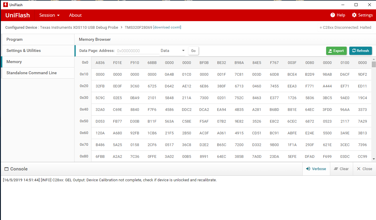
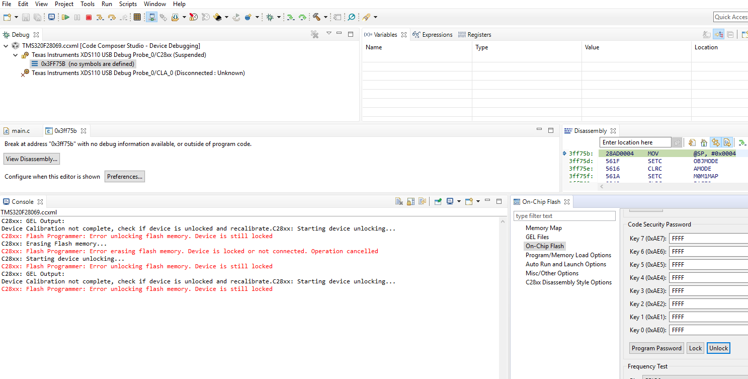
...but I've a warning about "Device Calibration".
If I try to enter debug session I can connect to MCU and view status but when I try to debug/donwload the code CCS send the error: C18xx: Flash programmer: Error unlocking flash memory. Device is still locked. MCU can not be unlocked and erased. The key pass is all set to 0xFFFF.
I tested:
1) Power supply. All are 3.3V stable;
2) Gound connections; All ok;
3) Error in mounting components. All ok;
4) JTAG pin connection;
I've tryed:
1) Replacing MCU with new one --> Still the same error;
2) Changing much connection configurations --> Still the same error;
I don't understand this behavior.
Anyone can help me please?
Best regards,