This thread has been locked.

If you have a related question, please click the "Ask a related question" button in the top right corner. The newly created question will be automatically linked to this question.

TMS320F28027: problems with SCI boot mode

Part Number: TMS320F28027

hi,

On our designs we are using TMS320F28027PT Piccolo.

Lately we've come across a strange behaviour regarding PWM output pins.

In SCI boot mode (which we establish via external push-button connected to a header) the PWM pins for the inverter module (pins 37-42) sometimes come high (with very random order and time delay), which can lead to high currents spikes durring programming the Piccolo.

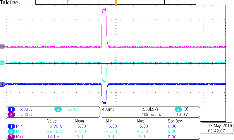
Channel 3 is the main current spike (one of the motor phases), and the channel 1 and 2 are the current spikes through the other 2 motor phases.

These spikes only occur in the SCI boot mode and never in the normal (operational) mode.

As you can see the peak current can reach up to 13A and higher, which kicks the motor a lot and can spin the PMSM quite aggressively for a few seconds.

The problem is that this behaviour is not repeatable, it occurs a few times and then nothing for some time, but after a while it happens again.

I've tried to replace the Piccolo and programm it, but the output was the same.

It is not necessary to programm the Piccolo for the current spikes to occur, only setting it to the SCI BOOT MODE state will trigger the effect.

What could cause the problem?

do you know any workaround?

Thanks a lot in advance

KR

Vincenzo


  • Vincenzo,

    By default all primary PWM pins have their internal PU disabled from reset to prevent turning on the FETs as you mention.  I looked into the SCI boot source in the ROM, and while the PU/MUX/Qual for GPA control are touched, only the SCI primary pins(GPIO28/29) are touched, so there should be no change to the internal PU for the  PWM pins(kept at 1, meaning the PU is disabled):

    The only other comment I have is that all pins are inputs at reset, so while we disable the PUs for the reason stated above, the pin is not driven from the C2000 until the pin configured as a PWM, which from reset would drive it low.  Since these are inputs, is it possible there is any feedback from the FET driver that might be latching a high state?

        // Enable pull-ups on SCI-A pins
        // GpioCtrlRegs.GPAPUD.bit.GPIO28 = 0;
        // GpioCtrlRegs.GPAPUD.bit.GPIO29 = 0;
        GpioCtrlRegs.GPAPUD.all &= 0xCFFFFFFF;
        // Enable the SCI-A pins   
        // GpioCtrlRegs.GPAMUX2.bit.GPIO28 = 1;
        // GpioCtrlRegs.GPAMUX2.bit.GPIO29 = 1;
        GpioCtrlRegs.GPAMUX2.all |= 0x05000000;
        // Input qual for SCI-A RX is asynch
        GpioCtrlRegs.GPAQSEL2.bit.GPIO28 = 3;


  • we found a mistake in layout routing... problem solved