


Tool/software: Code Composer Studio
Hi community
I have a question about PWM deadband. For controlling a power electronic inverter, in some control schemes, a voltage modulator (SVM or SPWM) is not used. Instead, the switching configuration of the inverter during a switching period is fixed. In other words, the state of each switch during the switching period is fixed : 100% ON or 100% OFF. A simple diagram is shown in the attached figure where 3 consecutive switching periods are shown. For implementing this control scheme using TMS320F28377D, theduty-cyle of ePWM in the code in every switching period is 100% (100% on or 100% off).
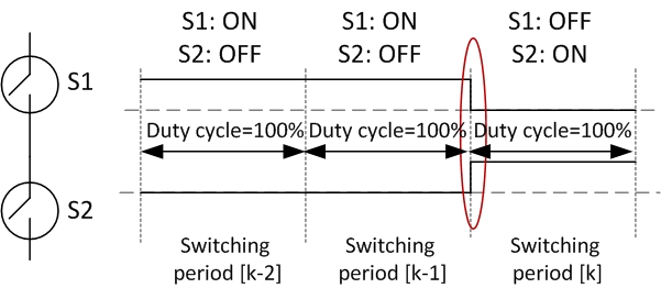
Now as you better know, in transitions of switching states of each pair of switches in a same leg of the inverter, there should be a dead-time (e.g the transition shown in the figure using a red ellipse ). This is implemented by the ePWM Deadband as discussed in TRM for duty cyles less than 100% (Fig. 13-34 Dead-Band Waveforms for Typical Cases (0% < Duty < 100%)). But the question is that how can we apply a dead-band for the cases that I have explained? (i.e., duty cycle =100%)
regards
