This thread has been locked.

If you have a related question, please click the "Ask a related question" button in the top right corner. The newly created question will be automatically linked to this question.

CCS/TMS320F280049: A question about 0049 Crystal oscillator

Part Number: TMS320F280049

Tool/software: Code Composer Studio

hi, 

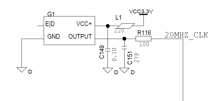
We are facing a question about Crystal oscillator of 0049.

the figure shows how we connect oscillator and c2000,

if we short the Capacitor, our C2000 would enter abnormal states:

  1. enter  Interrupt_defaultHandler
  2. enter NMI interrupt, Flag shows RAM, Flash, CLB have faults

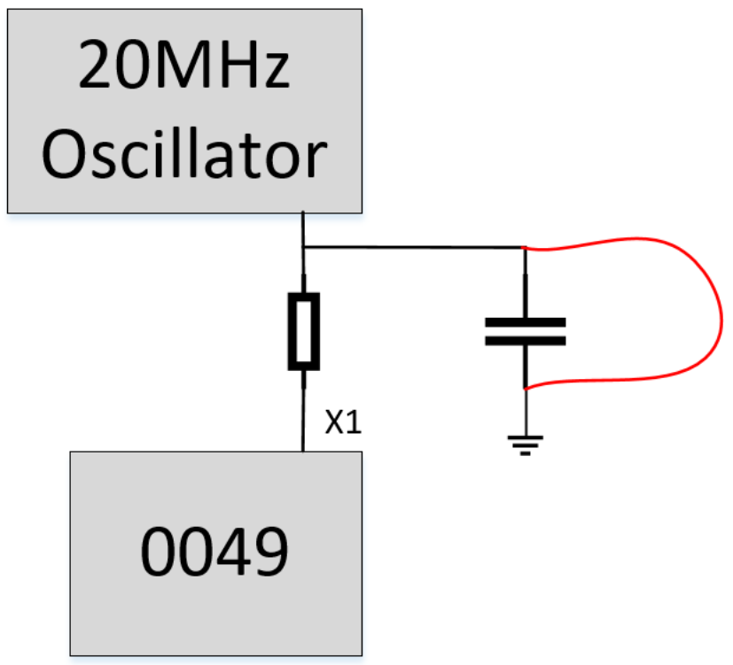
we hope to know, why these two states happened? why NMI didn't show CLK has fault?

Thank you ~

  • Hello,
    Concerned experts have been notified of this query.
    Note that TI US office is closed today so please expect a delayed response.


    Regards
    Himanshu
  • HI, We read more register, please see as below:

  • Hi Erwin,

    Based from the register configurations you have sent above, looks like clock is sourced from INTOSC2 (internal oscillator 2) [CLKSRCCTRL1.OSCCLKSRCSEL = 0]. This clock provides 10MHz to the PLL so if customer is shorting the clock input to F280049, device still has a clock, hence not reporting MCDOFF.

    Regards,
    Joseph
  • Hi Erwin,

    Have not heard back from you regarding this issue so I am assuming that you have resolved it hence marking this thread resolved.  If you still have any issues, please post it in the forum.

    Regards,

    Joseph

  • hi, Joseph

    sorry to reply you late, we double checked with my customer, here is customer's timer configuration:

    TIMER0 use an external oscillator for 20us interrupt;

    TIMER2 use an internal oscillator for 1ms interrupt;

    here is the code:

    configCPUTimer(CPUTIMER0_BASE, DEVICE_SYSCLK_FREQ, 20);   

    configCPUTimer(CPUTIMER2_BASE, INT1_OSC_CLK, 1000);     

    after oscillator disconnected with Ground, we found PWM1 was high for a long time, it's dangerous for our application.

    this is the waveform:

    Green: XRSN reset signal

    Blue: External oscillator output

    Red: PWM1

    if we do the test with debuger, when we short the oscillator to groud, we found the pointer stop at this address of BOOTROM, 

    RPC  0X3FC807

    PC   0X3FB02A

    Our question is,

    why PWM1 will output high level? 

    why program stop at this address?

    Thank you

  • Erwin,

    Let's put aside the PWM issue for now. I have a few questions:

    1. Why do you have a capacitor on the output of the oscillator. What is the value of this capacitor?

    2. In my experience, when registers are reading back 0xBAD, it means some power issue is going on. Have you monitored the VDDA/VDDIO and VDD power rails to make sure nothing strange is going on with them? You should also monitor XRSn.

    3. What oscillator are you using? Can you provide a zoomed in scope shot (a few cycles) of the oscillation?

  • hi, Frank,

    Please see my input:

    1. Why do you have a capacitor on the output of the oscillator. What is the value of this capacitor?

    the frequency is 20MHz, we connect C151 to ground, it's 27pF

    2. In my experience, when registers are reading back 0xBAD, it means some power issue is going on. Have you monitored the VDDA/VDDIO and VDD power rails to make sure nothing strange is going on with them? You should also monitor XRSn.

    Please see the waveform below, we didn't see any abnormal phenomena

    CH1: XRSN

    CH2: VDDIO C11

    CH3:VDDA C151

    CH4: 20MHz_CLK output

    What oscillator are you using? Can you provide a zoomed in scope shot (a few cycles) of the oscillation

    CH1: XRSN

    CH2: VDDIO C11

    CH3:VDDA C151

    CH4: 20MHz_CLK output

    3. What oscillator are you using? Can you provide a zoomed in scope shot (a few cycles) of the oscillation

  • Erwin,

    Thanks for providing the extra details. Your oscillator output looks ok. It does have a fair amount of overshoot and undershoot so you might want to look into terminating it properly.

    The more concerning part of the new information you provided is that i see XRSn dipping low a few times. This means the device is getting reset at least 3 times. Is this intentional? Is XRSn being driven externally by something else? I have circled the areas I'm referring to in your capture.

  • hi,Frank,

     XRSn is driven internally.

    Thank you

  • Erwin,

    Ok. If XRSn is driven internally, this means it's coming from the device. This could either be power related or the watchdog is not being handled. For debug purposes, can you make sure the watchdog is disabled?