This thread has been locked.

If you have a related question, please click the "Ask a related question" button in the top right corner. The newly created question will be automatically linked to this question.

CCS/TMS320F28335: Error ADC Sampling

Part Number: TMS320F28335

Tool/software: Code Composer Studio

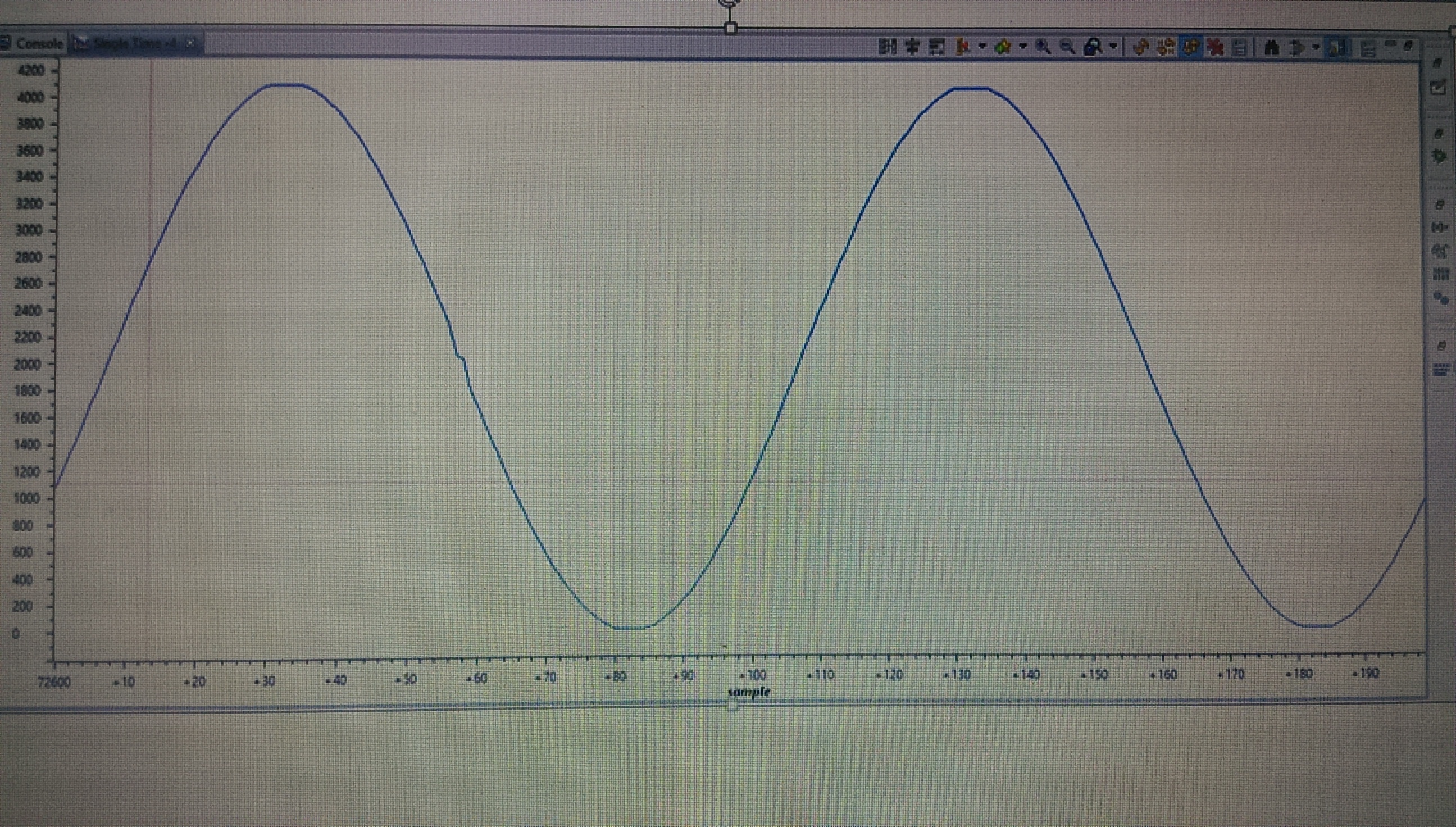
I'm traying to sample a current signal but I have a problem with the sample, the sample frequency is a 12kHz from the ePMW2 and the current signal is 60Hz, the next figure shown the signal sampled and the second figure is of a signal current of 65Hz and the signal of 65 Hz is distorted, I'm using a 200 data circular buffer

void InitAdc(void)
{
//--- Reset the ADC module
	AdcRegs.ADCTRL1.bit.RESET = 1;		// Reset the ADC

// Must wait 2 ADCCLK periods for the reset to take effect.  The ADC is 
// already reset after a DSP reset, but this example is just showing good
// coding practice to reset the peripheral before configuring it (as you
// never know why the DSP has started the code over again from the
// beginning).  Assuming a 12.5 MHz ADCCLK was previously configured, and
// a 150 MHz SYSCLKOUT, the wait period of 2 ADCCLK periods equates to 24
// CPU clocks.  This is the example being used below.
 
	asm(" RPT #22 || NOP");				// Must wait for ADC reset to take effect

//--- Call the ADC_cal() function located in the Boot ROM.
//    ADC_cal_func_ptr is a macro defined in the file example_nonBios.h or
//    example_BIOS.h (as may be the case for the example being used).  This
//    macro simply defines ADC_cal_func_ptr to be a function pointer to
//    the correct address in the boot ROM.
	(*ADC_cal_func_ptr)();

//--- Select the ADC reference
	AdcRegs.ADCREFSEL.bit.REF_SEL = 0;	// 0=internal, 1=external
	
//--- Power-up the ADC
	AdcRegs.ADCTRL3.all = 0x00EC;		// Power-up reference and main ADC
// bit 15-8      0's:    reserved
// bit 7-6       11:     ADCBGRFDN, reference power, 00=off, 11=on
// bit 5         1:      ADCPWDN, main ADC power, 0=off, 1=on
// bit 4-1       0110:   ADCCLKPS, clock prescaler, FCLK=HSPCLK/(2*ADCCLKPS)
// bit 0         0:      SMODE_SEL, 0=sequential sampling, 1=simultaneous sampling

	DelayUs(5000);						// Wait 5ms before using the ADC

//--- Configure the other ADC register
	AdcRegs.ADCMAXCONV.all = 0xB;

// For CPU servicing of ADC, we are only doing 1 conversion in the
// sequence.  So, we only need to configure the first channel
// selection in the sequence.  All other channel selection fields
// are don't cares in this example.
	AdcRegs.ADCCHSELSEQ1.bit.CONV00 = 0x0;	// Convert Channel 0
	AdcRegs.ADCCHSELSEQ1.bit.CONV01 = 0x1;
	AdcRegs.ADCCHSELSEQ1.bit.CONV02 = 0x2;
	AdcRegs.ADCCHSELSEQ1.bit.CONV03 = 0x3;
	AdcRegs.ADCCHSELSEQ2.bit.CONV04 = 0x4;
	AdcRegs.ADCCHSELSEQ2.bit.CONV05 = 0x5;
	AdcRegs.ADCCHSELSEQ2.bit.CONV06 = 0x6;
	AdcRegs.ADCCHSELSEQ2.bit.CONV07 = 0x7;
	AdcRegs.ADCCHSELSEQ3.bit.CONV08 = 0x8;
	AdcRegs.ADCCHSELSEQ3.bit.CONV09 = 0x9;
	AdcRegs.ADCCHSELSEQ3.bit.CONV10 = 0x10;

	AdcRegs.ADCTRL1.all = 0x0710;
// bit 15        0:      reserved
// bit 14        0:      RESET, 0=no action, 1=reset ADC
// bit 13-12     00:     SUSMOD, 00=ignore emulation suspend
// bit 11-8      0111:/1111   ACQ_PS (Acquisition), 0111 = 8 x ADCCLK
// bit 7         0:      CPS (Core clock), 0: ADCCLK=FCLK/1, 1: ADCCLK=FCLK/2
// bit 6         0:      CONT_RUN, 0=start/stop mode, 1=continuous run
// bit 5         0:      SEQ_OVRD, 0=disabled, 1=enabled
// bit 4         1:      SEQ_CASC, 0=dual sequencer, 1=cascaded sequencer
// bit 3-0       0000:   reserved


	AdcRegs.ADCTRL2.all = 0x0900;
// bit 15        0:      ePWM_SOCB_SEQ, 0=no action
// bit 14        0:       RST_SEQ1, 0=no action
// bit 13        0:      SOC_SEQ1, 0=clear any pending SOCs
// bit 12        0:      reserved
// bit 11        1:      INT_ENA_SEQ1, 1=enable interrupt
// bit 10        0:      INT_MOD_SEQ1, 0=int on every SEQ1 conv
// bit 9         0:      reserved
// bit 8         1:      ePWM_SOCA_SEQ1, 1=SEQ1 start from ePWM_SOCA trigger
// bit 7         0:      EXT_SOC_SEQ1, 1=SEQ1 start from ADCSOC pin
// bit 6         0:      RST_SEQ2, 0=no action
// bit 5         0:      SOC_SEQ2, no effect in cascaded mode
// bit 4         0:      reserved
// bit 3         0:      INT_ENA_SEQ2, 0=int disabled
// bit 2         0:      INT_MOD_SEQ2, 0=int on every other SEQ2 conv
// bit 1         0:      reserved
// bit 0         0:      ePWM_SOCB_SEQ2, 0=no action


//--- Enable the ADC interrupt
	PieCtrlRegs.PIEIER1.bit.INTx6 = 1;	// Enable ADCINT in PIE group 1
	IER |= 0x0001;						// Enable INT1 in IER to enable PIE group

} // end InitAdc()


//--- end of file -----------------------------------------------------

interrupt void ADCINT_ISR(void)					// PIE1.6 @ 0x000D4A  ADCINT (ADC)
{
static Uint16 *Current1Ptr = Current1;					// Pointer to ADC data buffer
static Uint16 *Current2Ptr = Current2;
static Uint16 *Current3Ptr = Current3;
static Uint16 *Current4Ptr = Current4;
static Uint16 *Current5Ptr = Current5;
static Uint16 *Voltage_ac1Ptr = Voltage_ac1;
static Uint16 *Voltage_ac2Ptr = Voltage_ac2;
static Uint16 *Voltage_ac3Ptr = Voltage_ac3;
static Uint16 *Voltage_dc1Ptr = Voltage_dc1;
static Uint16 *Voltage_dc2Ptr = Voltage_dc2;
static Uint16 *temperaturePtr = temperature;
static volatile Uint16 GPIO34_count = 0;		// Counter for pin toggle


	PieCtrlRegs.PIEACK.all = PIEACK_GROUP1;		// Must acknowledge the PIE group

//--- Manage the ADC registers
	AdcRegs.ADCTRL2.bit.RST_SEQ1 = 1;			// Reset SEQ1 to CONV00 state
	AdcRegs.ADCST.bit.INT_SEQ1_CLR = 1;			// Clear ADC SEQ1 interrupt flag
	AdcRegs.ADCTRL2.bit.RST_SEQ2 = 1;			// Reset SEQ2 to CONV08 state
    AdcRegs.ADCST.bit.INT_SEQ2_CLR = 1;			// Clear ADC SEQ2 interrupt flag

//--- Read the ADC result
		*Current1Ptr++= AdcMirror.ADCRESULT0;	// Read the result
		*Current2Ptr++ = AdcMirror.ADCRESULT1;
		*Current3Ptr++ = AdcMirror.ADCRESULT2;
		*Current4Ptr++ = AdcMirror.ADCRESULT3;
		*Current5Ptr++ = AdcMirror.ADCRESULT4;
		*Voltage_ac1Ptr++ = AdcMirror.ADCRESULT5;
		*Voltage_ac2Ptr++ = AdcMirror.ADCRESULT6;
		*Voltage_ac3Ptr++ = AdcMirror.ADCRESULT7;
		*Voltage_dc1Ptr++ = AdcMirror.ADCRESULT8;
		*Voltage_dc2Ptr++ = AdcMirror.ADCRESULT9;
		*temperaturePtr++ = AdcMirror.ADCRESULT10;

//--- Brute-force the circular buffer
	if( Current1Ptr == (Current1 + ADC_BUF_LEN) )
	{
		Current1Ptr = Current1;						// Rewind the pointer to the beginning

	}
	if( Current2Ptr == (Current2 + ADC_BUF_LEN) )
	{
		Current2Ptr = Current2;

	}
	if( Current3Ptr == (Current3 + ADC_BUF_LEN) )
	{
		Current3Ptr = Current3;
	}
	if( Current4Ptr == (Current4 + ADC_BUF_LEN) )
		{
		Current4Ptr = Current4;
		}
	if( Current5Ptr == (Current5 + ADC_BUF_LEN) )
			{
		Current5Ptr = Current5;
			}
	if( Voltage_ac1Ptr == (Voltage_ac1 + ADC_BUF_LEN) )
			{
		Voltage_ac1Ptr = Voltage_ac1;
			}
	if( Voltage_ac2Ptr == (Voltage_ac2 + ADC_BUF_LEN) )
		{
		Voltage_ac2Ptr = Voltage_ac2;
		}
	if( Voltage_ac3Ptr == (Voltage_ac3 + ADC_BUF_LEN) )
			{
		Voltage_ac3Ptr = Voltage_ac3;
			}
	if( Voltage_dc1Ptr == (Voltage_dc1 + ADC_BUF_LEN) )
			{
		Voltage_dc1Ptr = Voltage_dc1;
			}
	if( Voltage_dc2Ptr == (Voltage_dc2 + ADC_BUF_LEN) )
			{
		Voltage_dc2Ptr = Voltage_dc2;
			}
	if( temperaturePtr == (temperature+10) )
	{
		temperaturePtr = temperature;
	}
}

void InitEPwm(void)
{
//---------------------------------------------------------------------
//--- Must disable the clock to the ePWM modules if you       
//--- want all ePMW modules synchronized.
//---------------------------------------------------------------------
	asm(" EALLOW");						// Enable EALLOW protected register access
	SysCtrlRegs.PCLKCR0.bit.TBCLKSYNC = 0;
	asm(" EDIS");						// Disable EALLOW protected register access


//---------------------------------------------------------------------

//---------------------------------------------------------------------
	EPwm2Regs.TBCTL.bit.CTRMODE = 0x3;		// Disable the timer
	EPwm2Regs.TBCTL.all = 0xC033;			// Configure timer control register
// bit 15-14     11:     FREE/SOFT, 11 = ignore emulation suspend
// bit 13        0:      PHSDIR, 0 = count down after sync event
// bit 12-10     000:    CLKDIV, 000 => TBCLK = HSPCLK/1
// bit 9-7       000:    HSPCLKDIV, 000 => HSPCLK = SYSCLKOUT/1
// bit 6         0:      SWFSYNC, 0 = no software sync produced
// bit 5-4       11:     SYNCOSEL, 11 = sync-out disabled
// bit 3         0:      PRDLD, 0 = reload PRD on counter=0
// bit 2         0:      PHSEN, 0 = phase control disabled
// bit 1-0       11:     CTRMODE, 11 = timer stopped (disabled)

	EPwm2Regs.TBCTR = 0x0000;				// Clear timer counter
	EPwm2Regs.TBPRD = ADC_SAMPLE_PERIOD;	// Set timer period ADC_SAMPLE_PERIOD=SYSCLK/12kHz=12500-1=12449
	EPwm2Regs.TBPHS.half.TBPHS = 0x0000;	// Set timer phase

	EPwm2Regs.ETPS.all = 0x0100;			// Configure SOCA
// bit 15-14     00:     EPWMxSOCB, read-only
// bit 13-12     00:     SOCBPRD, don't care
// bit 11-10     00:     EPWMxSOCA, read-only
// bit 9-8       01:     SOCAPRD, 01 = generate SOCA on first event
// bit 7-4       0000:   reserved
// bit 3-2       00:     INTCNT, don't care
// bit 1-0       00:     INTPRD, don't care

	EPwm2Regs.ETSEL.all = 0x0A00;			// Enable SOCA to ADC
// bit 15        0:      SOCBEN, 0 = disable SOCB
// bit 14-12     000:    SOCBSEL, don't care
// bit 11        1:      SOCAEN, 1 = enable SOCA
// bit 10-8      010:    SOCASEL, 010 = SOCA on PRD event
// bit 7-4       0000:   reserved
// bit 3         0:      INTEN, 0 = disable interrupt
// bit 2-0       000:    INTSEL, don't care

	EPwm2Regs.TBCTL.bit.CTRMODE = 0;		// Enable the timer in count up mode


//---------------------------------------------------------------------
//--- Enable the clocks to the ePWM module.                   
//--- Note: this should be done after all ePWM modules are configured
//--- to ensure synchronization between the ePWM modules.
//---------------------------------------------------------------------
	asm(" EALLOW");							// Enable EALLOW protected register access
	SysCtrlRegs.PCLKCR0.bit.TBCLKSYNC = 1;	// HSPCLK to ePWM modules enabled
	asm(" EDIS");							// Disable EALLOW protected register access

} // end InitEPwm()


//--- end of file -----------------------------------------------------

. Could you tell me why is happen?. The code is below.

Current signal of 60Hz

Current signal of 65Hz

  • Juan,

    Are you using the exact same program for sensing the 60Hz and 65Hz input signals? I would not expect any discontinuity between 60Hz and 65Hz if using the same binary, and if the sampling rate is really 12kHz.

    Do you transition from 60Hz to 65Hz while continuously running the program (for example if using a function generator)? This should work too.

    -Tommy
  • Tommy,

    yes, I'm using the same program and also use the function generator, I only change the frequency while the program is running, the distortion doesn´t exist if the frequency is a multiple of 60Hz (for example, 60Hz, 120Hz, 180Hz...)

  • Juan,

    By disturbance, do you mean the sudden discontinuity in the sine wave? It is so abrupt that I suspect that it could be a circular buffer overwriting old data. If so, the signal should improve when setting a breakpoint on a line when the circular buffer is full and ready to wrap around.

    If irregularities coincide with multiples of 60Hz, it could be the AC mains power introducing noise. What if you configure the function generator to output a DC signal? Do you observe any issues?

    -Tommy

  • Tommy,

    With distortion I mean that the signal is cut off as seen in the second figure above, when the signal is multiple of 60Hz it works right but if the signal is not multiple of 60 60Hz those disturbances appear, when I configure the generator with signal of dc, the signal appears correctly ,there is not irregularities.
  • Juan,

    Based on the nature of the disturbance, I would recommend performing some additional system checks.

    Have you tried setting a breakpoint when the buffer is full and analyzing the static data?

    Can you check the input signal voltage and frequency using an oscilloscope?

    Another good exercise would be to toggle a GPIO pin or record the TBCTR in the ISR to make sure that the ADCRESULT is being read at the expected rate.

    -Tommy
  • //---  Toggle GPIO18 
    	if(DEBUG_TOGGLE == 1)
    	{
    
    		GpioDataRegs.GPATOGGLE.bit.GPIO18 = 1; //Toggle pin 18
    
    	}

    Tommy,

    Ok, a GPIO18 is toggle by the ISR  and the frequency of this pin  is 12kHz, I checked it with a oscilloscope. that part of the code is within the ISR ADC, on the other hand I always check the signal output of the generator with a oscilloscope. I took the data from the circular buffer and the graphs but the graph contains those incorrect values. 

  • Juan,

    Thanks for checking. I don't see anything obvious at this point. Does this happen on all ADC channels?

    -Tommy

  • Tommy,

    yes on all the ADC channels, for example the distortion appears on the ADC B channel too, for example you can see in the figure the B0 channel.

  • Juan,

    If it's all channels, I would recommend disabling all logging activity except for a single channel so that you can focus on it. This would also help to check for the possibility of inadvertent clobbering of data due to errors in pointer math.

    -Tommy
  • Tommy,

    disable all channels, except channel A0 and the result with a sinusoidal signal of 65Hz is the one seen in the figure, the same thing happens.

  • Juan,

    Can you attach your simplified program as a file?

    -Tommy

  • of course, the is below.

    void main(void)
    {
    //--- CPU Initialization
    	InitSysCtrl();						
    	InitGpio();							
    	InitPieCtrl();						
    	InitWatchdog();						
    
    //--- Peripheral Initialization
    	InitAdc();							
    	InitEPwm();							 
    
    //--- Enable global interrupts
    	asm(" CLRC INTM, DBGM");			// Enable global interrupts and realtime debug
    
    //--- Main Loop
    	while(1)							// endless loop - wait for an interrupt
    	{
    		
    		asm(" NOP");
    	}
    
    void InitAdc(void)
    {
    //--- Reset the ADC module
    	AdcRegs.ADCTRL1.bit.RESET = 1;		// Reset the ADC
     
    	asm(" RPT #22 || NOP");				// Must wait for ADC reset to take effect
    
    	(*ADC_cal_func_ptr)();
    
    //--- Select the ADC reference
    	AdcRegs.ADCREFSEL.bit.REF_SEL = 0;	// 0=internal, 1=external
    	
    //--- Power-up the ADC
    	AdcRegs.ADCTRL3.all = 0x00EC;		// Power-up reference and main ADC
    
    	DelayUs(5000);						// Wait 5ms before using the ADC
    
    //--- Configure the other ADC register
    	AdcRegs.ADCMAXCONV.all = 0x0;//0xB;//0x1010;// (num de conversión + 1) (0001=1+1=2Conv)
    
    	AdcRegs.ADCCHSELSEQ1.bit.CONV00 = 0x0;	// Convert Channel 0
    	
    	AdcRegs.ADCTRL1.all = 0x0710;//0x0710; //f10
    
    	AdcRegs.ADCTRL2.all = 0x494C;


    //--- Enable the ADC interrupt
    	PieCtrlRegs.PIEIER1.bit.INTx6 = 1;	// Enable ADCINT in PIE group 1
    	IER |= 0x0001;						// Enable INT1 in IER to enable PIE group
    
    } // end InitAdc()
    
    
    interrupt void ADCINT_ISR(void)					// PIE1.6 @ 0x000D4A  ADCINT (ADC)
    {
    static Uint16 *Current1Ptr = Current1;					// Pointer to ADC data buffer
    static volatile Uint16 GPIO34_count = 0;		// Counter for pin toggle
    
    	PieCtrlRegs.PIEACK.all = PIEACK_GROUP1;		// Must acknowledge the PIE group
    
    //--- Manage the ADC registers
    	AdcRegs.ADCTRL2.bit.RST_SEQ1 = 1;			// Reset SEQ1 to CONV00 state
    	AdcRegs.ADCST.bit.INT_SEQ1_CLR = 1;			// Clear ADC SEQ1 interrupt flag
    	/*AdcRegs.ADCTRL2.bit.RST_SEQ2 = 1;			// Reset SEQ2 to CONV08 state
        AdcRegs.ADCST.bit.INT_SEQ2_CLR = 1;			// Clear ADC SEQ2 interrupt flag*/
    
    //--- Read the ADC result
    		*Current1Ptr++= AdcMirror.ADCRESULT0;	// Read the result	
    
    //--- Brute-force the circular buffer
    	if( Current1Ptr == (Current1 + ADC_BUF_LEN) )
    	{
    		Current1Ptr = Current1;						// Rewind the pointer to the beginning
    
    	}
    	
    //--- Example: Toggle GPIO18 so we can read it with the ADC
    	if(DEBUG_TOGGLE == 1)
    	{
    
    		GpioDataRegs.GPATOGGLE.bit.GPIO18 = 1; //Toggle pin 18
    
    
    	}
    
    }
    
    void InitEPwm(void)
    {
    
    	asm(" EALLOW");						// Enable EALLOW protected register access
    	SysCtrlRegs.PCLKCR0.bit.TBCLKSYNC = 0;
    	asm(" EDIS");						// Disable EALLOW protected register access
    
    	EPwm2Regs.TBCTL.bit.CTRMODE = 0x3;		// Disable the timer
    	EPwm2Regs.TBCTL.all =0xC033;//0xC033;//0xC8B3;//0xC333; //0xC0BB;//0xC033;			// Configure timer control register
    
    	EPwm2Regs.TBCTR = 0x0000;				// Clear timer counter
    	EPwm2Regs.TBPRD = ADC_SAMPLE_PERIOD;	// Set timer period
    	EPwm2Regs.TBPHS.half.TBPHS = 0x0000;	// Set timer phase
    
    	EPwm2Regs.ETPS.all = 0x0100;			// Configure SOCA
    	EPwm2Regs.ETSEL.all = 0x0A00;			// Enable SOCA to ADC
    	EPwm2Regs.TBCTL.bit.CTRMODE = 0;		// Enable the timer in count up mode
    
    
    	asm(" EALLOW");							// Enable EALLOW protected register access
    	SysCtrlRegs.PCLKCR0.bit.TBCLKSYNC = 1;	// HSPCLK to ePWM modules enabled
    	asm(" EDIS");							// Disable EALLOW protected register access
    
    } // end InitEPwm()


  • Juan,

    The source is incomplete.  Please use the CCS>>File>>Export>>General>>Archive File wizard to create a ZIP of your project and attach it as a file.

    -Tommy

  • Juan,

    Do you see the disturbance on every sweep or does it take some number of iterations or time for it to present itself?

    -Tommy
  • Tommy,

    I see the disturbance in a short time or sometimes in a long time

  • Juan,

    I think you are just seeing artifacts in the graph refresh function through CCS. The continuous refresh of the graph is not guaranteed to operate synchronously with the circular buffer updates so you can see occasional "glitches" in the plot.

    You can confirm this by adding some code in your program to check for real disturbances in the sine wave data series:

    volatile Uint16 halt = 1;
    volatile Uint16 error = 65;
    Uint16 check1, check2;
    
    if( Current1Ptr == (Current1 + ADC_BUF_LEN) )
    {
        Current1Ptr = Current1;						// Rewind the pointer to the beginning
    
    }
    else
    {
        if(halt && (Current1Ptr > (Current1 + 2)))
        {
            check1 = *(Current1Ptr-1);
            check2 = *(Current1Ptr-2);
            if(abs(check1-check2) > error)
            {
                asm(" ESTOP0");  // Halt when disturbance is detected in the data series
            }
        }
    }

    -Tommy

  • Tommy,

    Ok, thanks Tommy, You helped me a lot, just one question, why 65 in the error variable?

  • Juan,

    65 was a reasonable threshold value for the disturbance check on my setup. I made it a volatile variable so that it is easy to empirically find a threshold value that works well on your own setup.

    The halt variable is helpful because the circular buffer will lose synchronization with the input signal whenever execution freezes at ESTOP. The buffer will need to flush (with halt=0) before checking for subsequent disturbances.

    -Tommy
  • Thanks for your answers Tommy.