This thread has been locked.

If you have a related question, please click the "Ask a related question" button in the top right corner. The newly created question will be automatically linked to this question.

TMS320F28035: DRV8312-C2-KIT with sensored BLDC motor

Part Number: TMS320F28035
Other Parts Discussed in Thread: CONTROLSUITE

Customer able to get his sensored motor spinning at a high rate with DRV8312-C2-KIT. This is a low inductance, hall-sensored motor. We were able to modify the code to speed up PWM and increase the speed control of the GUI in Hall-sensored mode. But we need help with optimization.

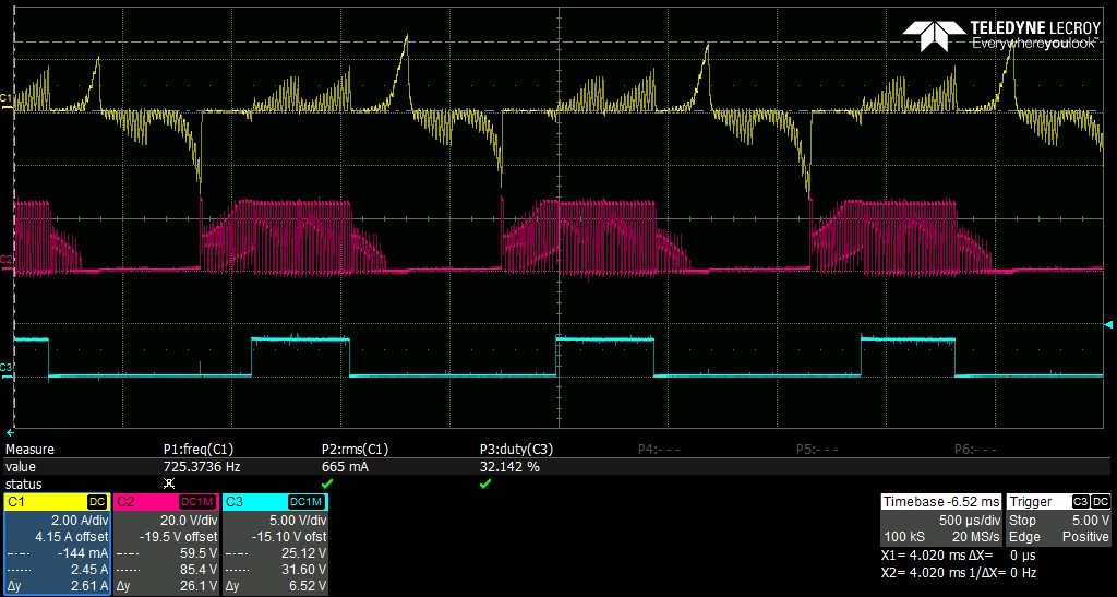
Here is a scope shot of motor waveforms while spinning. Top is phase current, middle is voltage and bottom is PWM_A out of the MCU. There is a large current spike and the voltage waveform looks like commutation is a little late. Do you agree?  and if so, how is the timing adjusted in the code?

  • As we have replied to you in another thread, what are the target speed and pole pairs of the motor?

    1. You need to use a higher PWM frequency (ISR frequency) for high speed since the example project checks the hall signal in PWM interrupt.

    2. You need to do calibration for the hall signal input since the hall signal input is not ideal commutation point for motor drive, the impaction can be ignored during high speed. The example project didn't do this and have such code, customer needs to do this by himself.

  • Hi Yanming,

    This is a different motor than my other post.  Customer is now using a sensed motor.

    Motor has 4 poles (2 pole pairs) and target speed is 25k RPM

    We already figured out how to increase the PWM frequency and have it running at 60 kHz.

    From the waveform do you agree that the commutation point may not be ideal? We are looking for confirmation.  

    Can you explain more your comment that the ideal commutation point can be ignored at high speed? 

  • The error of the commutation point is from the installation of the hall snesors, that means the interval time is not equal to 60 degrees between every output signal of the hall sensors if the speed is constant. You need to do calibration for the commutation point according to the output signal of the hall for every motor by yourself. As mentioned, the example project in controlSUITE is just a reference based on the ideal case.