This thread has been locked.

If you have a related question, please click the "Ask a related question" button in the top right corner. The newly created question will be automatically linked to this question.

TMS320F28035: C2000 Can bus bit timing

Part Number: TMS320F28035
Other Parts Discussed in Thread: C2000WARE

CAN Bit-Timing Configuration 

I am using 28379 at 500KHZ and using     CANBitRateSet(CANB_BASE, 200000000, 500000); to set the rate.

So to set the same baud rate for 28035 what should I have my registers for Setup.

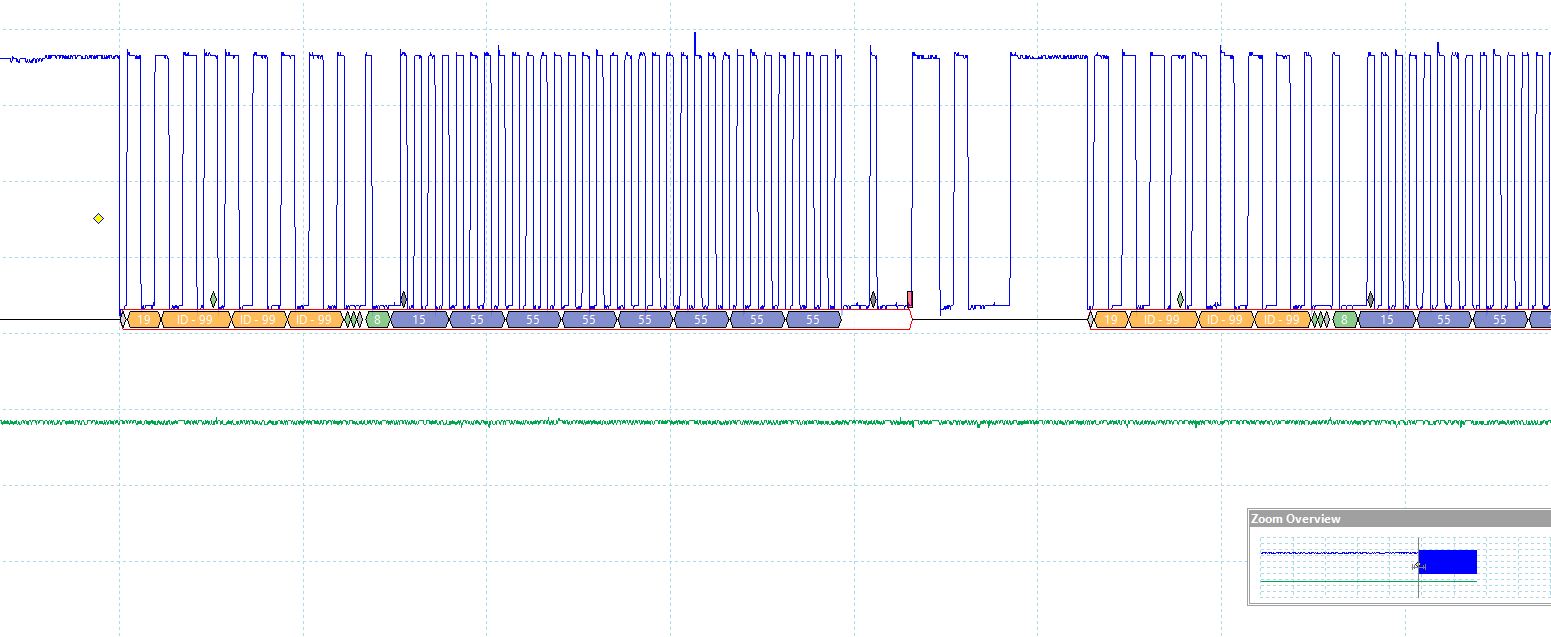
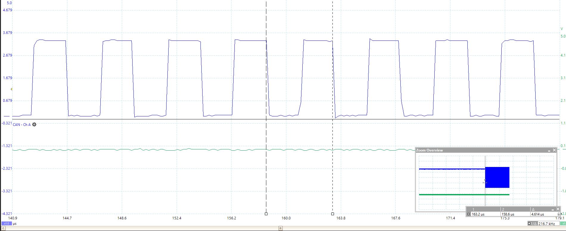
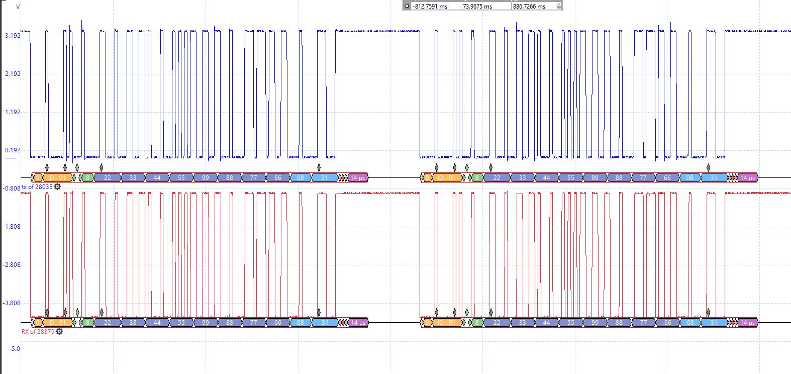
I feel the baud rate is not correctly set since I  send 8 bytes on mailbox 25 from 28035 to 28379 but it in 28379 code in the Rx interrupt I always get the error bit set. I think I might have not correctly set the baud rate. Can you verify  that? thanks

ECanaShadow.CANBTC.bit.BRPREG = 6;
ECanaShadow.CANBTC.bit.TSEG2REG = 1;
ECanaShadow.CANBTC.bit.TSEG1REG = 6;

  • Assuming you are operating 28035 at 60 MHz SYSCLKOUT frequency, i/p clock to CAN module is 30 MHz. This means [Bit-time x (BRPreg+1)] must be equal to 60, for 500 kbps. Changing BRPreg to 5 should make it work.

  • //
    // Included Files
    //
    #include "F28x_Project.h"
    #include <stdint.h>
    #include <stdbool.h>
    #include "inc/hw_types.h"
    #include "inc/hw_memmap.h"
    #include "inc/hw_can.h"
    #include "driverlib/can.h"
    
    //
    // Globals
    //
    volatile unsigned long g_ulTxMsgCount = 0; // A counter that keeps track of the
                                               // number of times the TX interrupt
                                               // has occurred, which should match
                                               // the number of TX messages that
                                               // were sent.
    volatile unsigned long g_ulRxMsgCount = 0;
    unsigned long u32CANBErrorStatus;
    volatile unsigned long g_bErrFlag = 0;     // A flag to indicate that some
                                               // transmission error occurred.
    tCANMsgObject sTXCANMessage;
    tCANMsgObject sRXCANMessage, sRXCANMessage2;
    unsigned char ucTXMsgData[8] ={ 0x00, 0x00, 0x00, 0x00, 0x00, 0x00, 0x00,
                                    0x00 };
    unsigned char ucRXMsgData[8];
    unsigned char ucRXMsgData2[8];
    unsigned long u32CntTXMsgData = 0x12345678;
    unsigned long errorTxERROR = 0;
    int flagRecv = 0;
    
    //
    // CANIntHandler - This function is the interrupt handler for the CAN
    //                 peripheral. It checks for the cause of the interrupt, and
    //                 maintains a count of all messages that have been
    //                 transmitted.
    //
    interrupt void
    CANIntHandler(void)
    {
        unsigned long ulStatus;
    
        //
        // Read the CAN interrupt status to find the cause of the interrupt
        //
        ulStatus = CANIntStatus(CANB_BASE, CAN_INT_STS_CAUSE);
    
        //
        // If the cause is a controller status interrupt, then get the status
        //
        if(ulStatus == CAN_INT_INT0ID_STATUS)
        {
            //
            // Read the controller status.  This will return a field of status
            // error bits that can indicate various errors.  Error processing
            // is not done in this example for simplicity.  Refer to the
            // API documentation for details about the error status bits.
            // The act of reading this status will clear the interrupt.  If the
            // CAN peripheral is not connected to a CAN bus with other CAN devices
            // present, then errors will occur and will be indicated in the
            // controller status.
            //
            ulStatus = CANStatusGet(CANB_BASE, CAN_STS_CONTROL);
    
            //
            //Check to see if an error occurred.
            //
            if(((ulStatus  & ~(CAN_ES_TXOK | CAN_ES_RXOK)) != 7) &&
               ((ulStatus  & ~(CAN_ES_TXOK | CAN_ES_RXOK)) != 0))
            {
                //
                // Set a flag to indicate some errors may have occurred.
                //
                g_bErrFlag = 1;
            }
        }
    
        //
        // Check if the cause is message object 1, which what we are using for
        // sending messages.
        //
        else if(ulStatus == 1)
        {
            //
            // Getting to this point means that the TX interrupt occurred on
            // message object 1, and the message TX is complete.  Clear the
            // message object interrupt.
            //
            CANIntClear(CANB_BASE, 1);
    
            //
            // Increment a counter to keep track of how many messages have been
            // sent.  In a real application this could be used to set flags to
            // indicate when a message is sent.
            //
            g_ulTxMsgCount++;
    
            //
            // Since the message was sent, clear any error flags.
            //
            g_bErrFlag = 0;
        }
    
        //
        // Check if the cause is message object 1, which what we are using for
        // receiving messages.
        //
        else if(ulStatus == 2)
        {
            //
            // Get the received message
    
            CANMessageGet(CANB_BASE, 1, &sRXCANMessage, true); // get the mail box recieved
    
            //
            // Getting to this point means that the TX interrupt occurred on
            // message object 1, and the message TX is complete.  Clear the
            // message object interrupt.
            //
            CANIntClear(CANB_BASE, 2);
    
            //
            // Increment a counter to keep track of how many messages have been
            // sent.  In a real application this could be used to set flags to
            // indicate when a message is sent.
            //
            g_ulRxMsgCount++;
    
            //
            // Since the message was sent, clear any error flags.
            //
            g_bErrFlag = 0;
        }
    
        //
        // Otherwise, something unexpected caused the interrupt.  This should
        // never happen.
        //
        else
        {
            //
            // Spurious interrupt handling can go here.
            //
        }
    
        CANGlobalIntClear(CANB_BASE, CAN_GLB_INT_CANINT0);
        PieCtrlRegs.PIEACK.all = PIEACK_GROUP9;
    }
    
    //
    // Main
    //
    int main(void)
    {
        //
        // Step 1. Initialize System Control:
        // PLL, WatchDog, enable Peripheral Clocks
        // This example function is found in the F2837xD_SysCtrl.c file.
        //
        InitSysCtrl();
    
        //
        // Step 2. Initialize GPIO:
        // This example function is found in the F2837xD_Gpio.c file and
        // illustrates how to set the GPIO to its default state.
        //
        InitGpio();
       /* GPIO_SetupPinMux(73, GPIO_MUX_CPU1, 3); // GPIO 73 - XCLKOUT
        GPIO_SetupPinOptions(73, GPIO_OUTPUT, GPIO_PUSHPULL); // SYSCLOCK/8 = 25MHz
        GPIO_SetupPinMux(30, GPIO_MUX_CPU1, 1); // GPIO30 - CANRXA
        GPIO_SetupPinMux(31, GPIO_MUX_CPU1, 1); // GPIO31 - CANTXA
        GPIO_SetupPinOptions(30, GPIO_INPUT, GPIO_ASYNC);
        GPIO_SetupPinOptions(31, GPIO_OUTPUT, GPIO_PUSHPULL);*/
    
        GPIO_SetupPinMux(17, GPIO_MUX_CPU1, 2); //GPIO12 -  CANRXB
        GPIO_SetupPinOptions(17, GPIO_INPUT, GPIO_ASYNC);
        GPIO_SetupPinMux(12, GPIO_MUX_CPU1, 2);  //GPIO17 - CANTXB
        GPIO_SetupPinOptions(12, GPIO_OUTPUT, GPIO_PUSHPULL);
    
        //
        // Initialize the CAN controller
        //
        CANInit(CANB_BASE);
    
        //
        // Setup CAN to be clocked off the PLL output clock (500kHz CAN-Clock)
        //
        CANClkSourceSelect(CANB_BASE, 0);
    
        //
        // Set up the bit rate for the CAN bus.  This function sets up the CAN
        // bus timing for a nominal configuration.  You can achieve more control
        // over the CAN bus timing by using the function CANBitTimingSet() instead
        // of this one, if needed.
        // In this example, the CAN bus is set to 500 kHz.  In the function below,
        // the call to SysCtlClockGet() is used to determine the clock rate that
        // is used for clocking the CAN peripheral.  This can be replaced with a
        // fixed value if you know the value of the system clock, saving the extra
        // function call.  For some parts, the CAN peripheral is clocked by a fixed
        // 8 MHz regardless of the system clock in which case the call to
        // SysCtlClockGet() should be replaced with 8000000.  Consult the data
        // sheet for more information about CAN peripheral clocking.
        //
        CANBitRateSet(CANB_BASE, 200000000, 500000); //500000*1 // Set the BAUD Rate here Same As 28035
    
        //
        // Enable interrupts on the CAN peripheral.  This example uses static
        // allocation of interrupt handlers which means the name of the handler
        // is in the vector table of startup code.  If you want to use dynamic
        // allocation of the vector table, then you must also call CANIntRegister()
        // here.
        //
        CANIntEnable(CANB_BASE, CAN_INT_MASTER | CAN_INT_ERROR | CAN_INT_STATUS);
    
        //
        // Step 3. Clear all interrupts and initialize PIE vector table:
        // Disable CPU interrupts
        //
        DINT;
    
        //
        // Initialize the PIE control registers to their default state.
        // The default state is all PIE interrupts disabled and flags
        // are cleared.
        // This function is found in the F2837xD_PieCtrl.c file.
        //
        InitPieCtrl();
    
        //
        // Disable CPU interrupts and clear all CPU interrupt flags:
        //
        IER = 0x0000;
        IFR = 0x0000;
    
        //
        // Initialize the PIE vector table with pointers to the shell Interrupt
        // Service Routines (ISR).
        // This will populate the entire table, even if the interrupt
        // is not used in this example.  This is useful for debug purposes.
        // The shell ISR routines are found in F2837xD_DefaultIsr.c.
        // This function is found in F2837xD_PieVect.c.
        //
        InitPieVectTable();
    
        //
        // Interrupts that are used in this example are re-mapped to
        // ISR functions found within this file.
        // Register interrupt handler in RAM vector table
        //
        EALLOW;
        PieVectTable.CANB0_INT = CANIntHandler;
        EDIS;
    
        //
        // Enable the CAN interrupt on the processor (PIE).
        //
        PieCtrlRegs.PIEIER9.bit.INTx7 = 1;
        IER |= 0x0100;   // M_INT9
        EINT;
    
        //
        // Enable test mode and select external loopback
        //
    
    
        //HWREG(CANB_BASE + CAN_O_CTL)|= CAN_CTL_IE0;
         //HWREG(CANB_BASE + CAN_O_CTL) |= CAN_CTL_TEST;
        //  HWREG(CANB_BASE + CAN_O_TEST) = CAN_TEST_EXL;
    
    
        //
        // Enable the CAN for operation.
        //
        CANEnable(CANB_BASE);
    
        //
        // Enable CAN Global Interrupt line0
        //
        CANGlobalIntEnable(CANB_BASE, CAN_GLB_INT_CANINT0);
    
        //
        // Initialize the message object that will be used for sending CAN
        // messages.  The message will be 4 bytes that will contain an incrementing
        // value.  Initially it will be set to 0x12345678.
        //
        // Initialize the message object that will be used for receiving CAN
        // messages.
        //
        *(unsigned long *)ucRXMsgData = 0;
        sRXCANMessage.ui32MsgID = 1;                      // CAN message ID - use 1
        sRXCANMessage.ui32MsgIDMask = 0;                  // no mask needed for TX
        sRXCANMessage.ui32Flags = MSG_OBJ_RX_INT_ENABLE;  // enable interrupt on RX
        sRXCANMessage.ui32MsgLen = 8;//sizeof(ucRXMsgData);   // size of message is 8
        sRXCANMessage.pucMsgData = ucRXMsgData;           // ptr to message content


        //
        // Setup the message object being used to receive messages
        //
        //CANMessageSet(CANB_BASE, 2, &sRXCANMessage, MSG_OBJ_TYPE_RX); // 2 IS THE MAIL BOX NUMBER
    
        //
        // Send the CAN message using object number 1 (not the same thing as
        // CAN ID, which is also 1 in this example).  This function will cause
        // the message to be transmitted right away.
        //


        while(1){
            CANMessageGet(CANB_BASE, 1, &sRXCANMessage, true);
            DELAY_US(1000*100);
        }
    
    }
    
    //EOF
    //28035 code test
    
    #include "DSP28x_Project.h"     // Device Headerfile and Examples Include File
    
    #define TXCOUNT  100000  // Transmission will take place (TXCOUNT) times..
    
    long      i;
    long      loopcount = 0;
    
    main()
    {
    
    /* Create a shadow register structure for the CAN control registers.
    
    This is needed since only 32-bit access is allowed to these registers. 16-bit access
     to these registers could potentially corrupt the register contents. This is
     especially true while writing to a bit (or group of bits) among bits 16 - 31 */
    
    struct ECAN_REGS ECanaShadow;
    
    /* Kill Watchdog, Init PLL, Enable peripheral clocks */
    
        InitSysCtrl();
    
    /* Initialize the CAN module */
    
        InitECana();
        InitECanGpio();
    
        EALLOW;
    
    /* Write to the MSGID field  */
    
        ECanaMboxes.MBOX1.MSGID.all = 0x99999999; // Extended Identifier
    
    /* Configure Mailbox under test as a Transmit mailbox */
    
        ECanaShadow.CANMD.all = ECanaRegs.CANMD.all;
        ECanaShadow.CANMD.bit.MD1 = 0;
        ECanaRegs.CANMD.all = ECanaShadow.CANMD.all;
    
    /* Enable Mailbox under test */
    
        ECanaShadow.CANME.all = ECanaRegs.CANME.all;
        ECanaShadow.CANME.bit.ME1 = 1;
        ECanaRegs.CANME.all = ECanaShadow.CANME.all;
    
    /* Write to DLC field in Message Control reg */
    
        ECanaMboxes.MBOX1.MSGCTRL.bit.DLC = 8;
    
    /* Write to the mailbox RAM field */
    
         ECanaMboxes.MBOX1.MDL.all = 0x55555555;
         ECanaMboxes.MBOX1.MDH.all = 0x55555555;
    
    /* Begin transmitting */
    
        while(1)                                // Uncomment this line for infinite transmissions
        //for(i=0; i < TXCOUNT; i++)                // Uncomment this line for finite transmissions
        {
         ECanaShadow.CANTRS.all = 0;
         ECanaShadow.CANTRS.bit.TRS1 = 1;     // Set TRS for mailbox under test
         ECanaRegs.CANTRS.all = ECanaShadow.CANTRS.all;
    
         ECanaShadow.CANTA.all = ECanaRegs.CANTA.all;
            do { ECanaShadow.CANTA.all = ECanaRegs.CANTA.all;
    
            }   // Wait for TA1 bit to be set..
             while(ECanaShadow.CANTA.bit.TA1 == 0 );
    
         ECanaShadow.CANTA.all = 0;
         ECanaShadow.CANTA.bit.TA1 = 1;         // Clear TA5
         ECanaRegs.CANTA.all = ECanaShadow.CANTA.all;
    
         loopcount ++;
        }
         asm(" ESTOP0");
    }
    

  • Not sure why you have posted your code. In general, we do not review or debug user code, but we will provide assistance to you with specific issues relating to our devices and development tools. This includes clarifying the behavior of any bit, register, or features when designing with our devices. Please note that all peripherals have example code in C2000Ware. We suggest comparing your code to the example code to determine where the problem may exist. It is recommended to follow standard and logical debugging techniques. Please continue to debug your code and feel free to use this forum to ask specific questions. The more specific the question, the better we can assist you.

  • I think I posted a question with this but it did not get posted. My question is in the above sample code which I have used from C2000ware. I am not receiving Acknowledge bit Set on 28035 code but interrupt in 28379 gets called every time 28035 send Tx msg.

    Also below in 28035 how many times it retry to send the data before getting Ack, (As a test I removed the CAN H and CAN L cable from 28379 but still 28035 continued to send data. 

    ECanaShadow.CANTA.all = ECanaRegs.CANTA.all;
            do { ECanaShadow.CANTA.all = ECanaRegs.CANTA.all;
            }   // Wait for TA1 bit to be set..
             while(ECanaShadow.CANTA.bit.TA1 == 0 );

    I was able to communicate between two launchpads 28379 but was unsuccessful between 28035 and 28379.

  • Have you reviewed the Debug tips in SPRA876?

    Also below in 28035 how many times it retry to send the data before getting Ack,

    Forever.

    Please capture the waveform on CANTX pin on 28035 and send it. The waveform must be very clear like it is in SPRACE5. Specifically, I am interested in looking at the bit-period on the 28035 end. Do this experiment when 28035 is not connected to 28379. Mismatched bit-rate between nodes will cause lot of bus errors

  • Is this the output on CANTX pin of 28035? Looks OK but could you provide a scope capture. Would like to look at the bit-width.

  • Yes this from TX pin of 28035.

    Below is Screenshot when I have 28035 in TX mode and my blue pin connected to TX of 28035.

    Red is Rx from Transceiver on Launchpad of 28379 where I receive signal. So looks like all hw configuration is correct.

    on 28035 side I have put 

    ECanaShadow.CANBTC.bit.BRPREG = 5;
    ECanaShadow.CANBTC.bit.TSEG2REG = 1;
    ECanaShadow.CANBTC.bit.TSEG1REG = 6;

    While on  CANBitRateSet(CANB_BASE, 200000000, (500*1000));.

    So if I put Break point on RX ISR of 28379 it stops and sets error bit. the value of this CANStatusGet(CANB_BASE, CAN_STS_CONTROL)  does not equal to 2. 

  • 4.614/2 = 2.307 uS, which translates to 433.463 kbps. I think 28379 operates at 500 kbps. It appears you didn't change the CANBTC values per my suggestion.

  • I think I did the same exact values as you mentioned and I have updated my last post with register values.

    I think I measured incorrectly before. Check the timing currently. 

    Also, Tseg1 and Tseg2 of 28035 has to be the same with 28379(i haven't modified anything in 28379?  

  • Now the bit-rate looks correct (500 kbps). TSEG1 & TSEG2 adjust the sampling-point for the bit. SP should be chosen based on the bus length, prop delay of transceivers, bit-rate etc. That is network dependent. Have you looked at the Debug tips in SPRACE5 and tried out the suggestions? If not, please try those first.

  • I did check SPRACE5. I am first Testing it with jumper cable of length approx 15mm. My question is that Since I do not Set the TSEG1 and TSEG2 on 28379, will this be a problem? I do it on 28035 which would make it not match exactly.

    The RX on Transceiver of 28379 has the correct data but it is not getting stored in the mailbox. Even if I manually try to get data from that mailbox it doesn't work.

    I tried using another mailbox and still, I had that problem. 

  • Since I do not Set the TSEG1 and TSEG2 on 28379, will this be a problem? I do it on 28035 which would make it not match exactly.

    You may not realize it, but the Driverlib function you are using does set those values. Examine CANBTR register value in CCS to decipher the values. (I have explained this clearly in pages 13 & 14 of SPRACE5).


    The RX on Transceiver of 28379 has the correct data but it is not getting stored in the mailbox. Even if I manually try to get data from that mailbox it doesn't work.

    So you are saying correct data is seen all the way up to CANRX pin of 28379 (since RX on transceiver is connected to CANRX of 28379), but it is not received in 28379. Did you directly see the mailbox RAM area in CCS memory window?


    I tried using another mailbox and still, I had that problem.

    I see that the MSGID on the 28035 side is 0x19999999, but MSGID on the 28379 side is 1. Reception will not work in this case.

  • 1.okay, your first point makes sense but I was concerned if Driver lib func set something else compared to 28035. I will check CanBTR in CCS to confirm again.

    2. I have seen in scope. I had posted a screenshot of tx pin of 28035 and Rx pin 28379 and posting again here. Is there any way I can see Mailbox RAM area on CCS?

    3)yes I made msg ID constant to 0x01 on both ends.

    Thanks,

  •  


    your first point makes sense but I was concerned if Driver lib func set something else compared to 28035. I will check CanBTR in CCS to confirm again.

    You can manually write to the timing register on either device and make the TSEG values identical.


    I have seen in scope. I had posted a screenshot of tx pin of 28035 and Rx pin 28379 and posting again here. Is there any way I can see Mailbox RAM area on CCS?

    The scope waveform must be very clear. One channel should show the CANTX pin of 28035 and the other channel should show the CANRX pin of 28035. The waveforms must be identical on both channels, with the exception of the ACK bit. See Fig 4 of SPRACE5. That is how clear the waveforms should look like. Your waveform doesn’t look like it was captured on a scope. What tool do you use?


    yes I made msg ID constant to 0x01 on both ends.

    Below from your code snippets:


    28379 side:

    sRXCANMessage.ui32MsgID = 1;                     // CAN message ID - use 1

    28035 side:

    ECanaMboxes.MBOX1.MSGID.all = 0x99999999; // Extended Identifier


    Beyond this, I have no ideas to help you.

  • 1)I am using a PicoScope to capture the signal.

    2)So the waveform I shared doesn't represent the correct form of communication? It looks like it is the same signal but I am capturing at 28035 Tx Transceiver and 28379 RX Transiever and I am using VP234 as Transceiver. 

    3) Yes, I have updated ECanaMboxes.MBOX1.MSGID.all = 0x00040000; on 28035. 

    tCANMsgObject sRXCANMessage; 

    sRXCANMessage.ui32MsgID = 0x00040000; Should make it to 0x01 right in 28379D ?

    Is there a way I can See if there Mailbox Ram directly?

    Thanks,

  • 2)So the waveform I shared doesn't represent the correct form of communication? It looks like it is the same signal but I am capturing at 28035 Tx Transceiver and 28379 RX Transiever and I am using VP234 as Transceiver.


    No. I clearly mentioned as follows in my previous post:

    "One channel should show the CANTX pin of 28035 and the other channel should show the CANRX pin of 28035. The waveforms must be identical on both channels, with the exception of the ACK bit".

    SPACE5 explains why and there is even a scope shot that clearly identifies the ACK signal. 

    I suggest you download the latest version of C2000ware and try out the examples that are part of SPRACE5. 

    Is there a way I can See if there Mailbox Ram directly?

    Yes, all you need to do is to display the Mailbox RAM area in the Memory window of CCS. Below image shows the RAM area starting from Mailbox 1:

  • Closing thread due to inactivity.