This thread has been locked.

If you have a related question, please click the "Ask a related question" button in the top right corner. The newly created question will be automatically linked to this question.

TIDM-HV-1PH-DCAC: ADC Sensing - Incorrect readings

Part Number: TIDM-HV-1PH-DCAC
Other Parts Discussed in Thread: TMDSCNCD28379D, C2000WARE, SFRA

Hi There,

I have the eval board in its baseline configuration, no hardware changes etc.

I am stepping through the TIDUAY6D (Revised May 2019) and have an inconsistency between the measured value and the actual value for the DC Bus.

I downloaded the project from the solutions adapter (Single Phase Inverter: Voltage Source TMS320F2837x),

I have also set the Project Non Modifiable Flag to 0 in kit.xml file plus have created an empty .cookie file in the project folder;

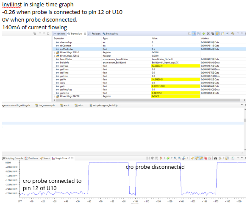
The guiVbus is reading approximately 10% higher than actual (confirmed with DMM).

Sensing was set to ADC.

I've tried changing the voltage sense resistor values (Ra and Rb), rebuilding and running the new project etc. unfortunately to no avail. i.e. guiVbus is still reading 10% high

I have also noticed that guiPrms, guiVrms and guiIrms are all inaccurate as well, however I thought I would start with the Vbus aspect first.

Thankyou

Robin

  • I was digging around looking at the code and how the guiVbus was being calculated and saw the following lines of code in the voltagesourceinvlcfltr.c file :

    guiVbus=invVbusInst*VAC_MAX_SENSE;

    guiVo=invVoInst*VDCBUS_MAX_SENSE;


    I believe these two variables have been swapped around, i.e. Vbus should be tied to VDCBUS_MAX_SENSE and Vo should be linked to VAC_MAX_SENSE;

    Please advise;


    Thanks

    Robin

  • Robin,

    I will refer this to our team member who developed this s/w. But he is on vacation for couple of days. So the response might be delayed for few days.

    Shamim

  • Thankyou

    I did end up swapping around the variables above and now am able to get changes to the Vbus reading when I change the Ra value in main.cfg.

    I was also able to get closer approximation (<1%) with the Vrms reading by changing Rc resistor value in main.cfg.

    Unfortunately I was not able to have the same success (>50%) with the Irms (and assumed Prms cause of its dependency on Irms).

    I'm a bit wary of the operations I performed above as I had presumed that the baseline board and the baseline code would all work straight out of the box/off the web.

    Regards

    Robin

  • Hello,

    I've done so more investigations and have noticed the following:

    Oscilloscope placed on TP18, which is the output from the OP AMP to the MCU; Inputs to the OP AMP are the outputs from the current sensor

    Monitoring this pin (I.inv), and it sits predominantly at 1.65V (expected), and when I change the current throughput I can see changes on the oscilloscope (e.g. from 0 amps to 0.5 amps AC rms);

    I also watched expression invIiInst in the expressions watcher and ran the project;

    I noticed that the invIiInst did not seem to reflect any changes in current flow, e.g. switching load on and off did not cause any effects on the invIiInst variable;

    I'll hunt down the pin allocations to the ADC and chack that the hardware aligns with the firmware.

    Robin

  • I checked the firmware against the as-built and confirmed that the ADC mapping was correct.

    I also selected SDFM and was able to get much more accurate voltage/current and wattage readings;

    Switching back to ADC and the readings head south in accuracy;

    I have some cro screenshots, however previous attempts at pasting to the forum have failed (not getting pasting from Word? trying to paste from clipboard)

    Regards

    Robin

  • Robin,

    did you check that 3.3V ref is selected for the controller? There is an option to use VDD and Vref, see 3.1.1.2

    http://www.ti.com/lit/ug/tiduay6d/tiduay6d.pdf

    Regards

    Manish

  • Hi Manish,

    The control card is in its default configuration, as follows:

    SW2-A (lower) set to right

    SW2-B (upper) set to right

    SW3-C (lower) set to right

    SW3-D (upper) set to right

    Reading the para in control card PDF (Table 2) and that seems to mean that ADC REF is using an external voltage as reference.

    Which I think is in the correct position for the inverter?

    Rgards

    Robin

  • both voltages are external,

    see

    C:\ti\C2000Ware_DigitalPower_SDK_1_03_00_00\c2000ware\boards\controlCARDs\TMDSCNCD28379D

    infosheet, 

    section hardware references, 

    The switches should be on left side for 3.3V ref SW2/3

    -Manish

  • Thanks Manish.

    I moved the switches to the left for all 4 switches then powered up the eval board.

    Repeating Build 1, Output = AC, Sensor = ADC :

    Now guiVbus is reading spot on, unfortunately the current and power values are still out of whack:

    i.e. guiPrms displays 4.36, but I am measuring 153 watts

    guiIrms displays 0.04, but I am measuring ~1.35

    Regards

    Robin

  • Took the opportunity to repeat the testing, except selecting SDFM as the sensor, and the current and power readings were accurate;

    I then attempted Build 2 (with SDFM) and hit that issue I was having (as per that other thread) where the invliinst was not track InvREF; I tried both the modelled data and the SFRA data from 2016 CSV file; I then halted any further Build 2 testing;

    As an FYI, I re-copied the VSI firmware across from the the powerware SDK folder and did a fresh rebuild, unfortunately still have issues with current and power readings when using ADC as the sensor.

    I am out of the office for a few days, back next week;

    Cheers

    Robin

  • Robin,

    Please do confirm

    1. This was a new board, I want to be sure we are not dealing with a build issue here

    2. On our end, I have asked a colleague of mine to test this on his end. 

    regards

    Manish 

  • Hi Manish,

    Yes I purchased the board from digikey sometime within the last six months.

    I can dig up the exact date if you require, or perhaps some build label on the CCA itself?

    Cheers

    Robin

  • Thanks Robin, At this point no need. Can you let us know your latest status on this now? 

  • Okay, following the user guide (TIDUAY6D Revised May 2019) for the inverter eval board, I was unable to complete Build 1 sequence of steps successfully, as the current and power readings were an order of magnitude out from actuals.

    Vbus is now reading correctly. (following the change to VREF configuration settings on the MCU board)

    ADC is the sensing method.

    I have reverted back to baseline firmware.

    Thanks

    Robin

  • Robin, 

    Ok, considering Vref is now in range. Can you elaborate on how much is the error now ?

    You can run the build level 1 under DC and see the sensing more precisely.

  • Hi Manish,

    The last set of readings I took were:

    guiPrms displays 4.36W, but I measure 153W

    guiIrms displas 0.04, but I measure 1.35A

    I will set build to DC and repeat;

    Regards

    Robin

  • Thanks , DC test will help up to isolate the true HW error. Will wait for your feedback. 

  • Hi Manish,

    DC mode set for Build 1;

    guiVbus=380, aligns with what was set on the PSU;

    guiPrms = 0

    guiVrms=0

    guiIrms=0, measured 1.59A via current clamp over one of the wires feeding the 110 ohm resistor

    guiVo = 183, measured 185Vdc.

    Not sure whether those guiXrms values are calculated when AC only, or whether there is some DC INPUT threshold I have to be over?

    Cheers

    Robin

  • Have worked out how to paste images...

    This screenshot is of invIiInst input to ADC A2, with me toggling Vbus voltage between 0 and 380VDC, current transitions between 0A and 1.64ADC, measured at the resistive load.

    This screenshot is of the output form the current sensor / input to the opamp, pin 12 of U10. Seems to indicate some sort of loading issue? Wasn't expecting it as the probes are high impedance...

    Time is getting away on me, I had expected to have resolved this by now (I had assumed it was human error on my behalf, however the longer it takes to resolve the less I am inclined to believe this)

    Robin

  • Robin,

    For the DC check, please check the instantaneous values, guiVo and guiIi, this will give you an idea of how much off you are on the board.

    guiVo=invVoInst*VDCBUS_MAX_SENSE;
    guiIi=invIiInst*I_MAX_SENSE;

    I'll recommend not connecting any probes that are not mentioned in the UG as that puts the board under conditions that it was not tested with. 

    -Manish 

  • Hi Manish,

    I set the Vbus level such that I had 0.5amps output to the resistive load.

    Vo (measured) = 59.9VDC

    Iinst(measured) = 0.5Arms

    Wrt the probes, I'll stick with the TPs, but i was cognisant of introducing any ground loops etc through the cro ref lead.

    Thanks

    Robin

  • Robin, 

    I'll probably pass the Vac sense as well, but Ii should be better. As I am unable to determine the issue, i will approve a replacement of the board.

    You will need to contact the channel through which you got the board for a replacemet and point them to this thread.  

    Regards

    Manish 

  • Thanks Manish

    I'll kick off the replacement board now.