This thread has been locked.

If you have a related question, please click the "Ask a related question" button in the top right corner. The newly created question will be automatically linked to this question.

MOTORWARE: Variable switching frequency

Part Number: MOTORWARE
Other Parts Discussed in Thread: TMS320F28069

Hello,

I wrote this post some time ago:

https://e2e.ti.com/support/microcontrollers/c2000/f/171/t/758193

Asking for some information on how to do the variable switching frequency for motor control. I have just recently starting to make the changes for this and I have a couple questions about it. I have seen the example project (TMS320F28004x) for the C2000 motor control SDK and I am trying to port that over to the TMS320F28069 and I have noticed that the estimator is taken out to a separate interrupt service routine. Why is this? Does the ISR for the estimator need to be constant? or can it vary? If it needs to be constant, does it have to be always higher than the maximum switching frequency expected? Is there any risk for having the estimator running at different frequency than the controller? I also noticed that within the estimator interrupt the speed PID is being run, is it needed for the estimator to work ok? or could it be run on the controller ISR?

Thanks!

  • 1. Right, the ISR for the estimator must be constant, so it needs a separate ISR, and it's better to use a higher frequency than PWM frequency.

    2. Not any risk if the frequency of the estimator is constant.

    3. Don't need to change the gains according to the control frequency if the PI regulator is run in ISR of the estimator. The gains of the PI must change if it is run in the controller ISR.

  • Thanks for the quick response.

    On that example project for the new Motor Control SDK the current PIDs (d and q) are run on the ISR. Does that mean that those gains also need to be adjusted with the control frequency?

  • That's tight if the PWM frequency is changed in a wide range and you want to get a better response performance, but it is not necessary to be adjusted in ISR. The action is done in computeCurrentControllers() in background loop.

  • Could the speed PID also be adjusted in the background loop the same way the current PIDs are updated?

  • The gains of both PIs can be adjusted in the background loop, but it's better to run the PIs in ISR with a precise timer since the background loop maybe not executed in a fixed period timer if the most CPU bandwidth is occupied by ISR.

  • I have one more question about this. Regarding the two interrupts, which one should have higher priority? Does it matter if one gets interrupted by the other one?

  • You should reserve enough CPU bandwidth to ensure that there are not any one of both interrupts will be missed, so you don't need to care which interrupt has higher priority. Of course, you may set the ADC interrupt to a higher one.

  • Hi,

    I am carrying on with this and I managed to get something that works. I ended up having two prioritized interrupts so that the ADC interrupt can interrupt the estimator one and seems to work reasonably well. I have however run into some problems when running at higher speeds and I think it is due to the way the angle delay compensation is done.

    Originally, we would run the CTRL_angleDelayComp function within the CTRL_run function to compensate for delays at high speeds. However in the is12_variable_pwm_frequency SDK example project this delay compensation is moved to the estimator ISR and also loos a little bit different. I am trying to understand how the new delay compensation works but I am not too sure. 

    It basically multiplies the speed by a factor which is 0.5*USER_CTRL_PERIOD_sec. Why is this? Is it compensating from the time it reads the initial angle value at the beginning of the interrupt with respect to the point it exits the interrupt? Is this where the 0.5 comes from? Does that assume that the ISR takes 0.5*USER_CTRL_PERIOD_sec seconds to execute?

    Taking into account my different approach with the two ISRs. Would it be better/worth it do the delay compensation using a timer that gets reset at the time the angle is first calculated and then read at the point of running the controller using the time difference for the compensation?

    Also, as a side question, in the mentioned project, the pwm period is updated right before writing the duty cycle to the PWM registers in the ADC interrupt from the VSF module. Would not be better to update the pwm period after that? The reason being, if the controller has already ran thinking it had a set PWM period, and then right before writing to the PWM registers you change it, you would be using a duty cycle calculated with a previous PWM period, isn't?

    Thanks for the help

  • Anyone?

    Also, even though it does seem to work ok. When I try high current I started to get some overcurrent trips (even at low speeds so I guess this might not be related to the delay compensation). I don't know if it has anything to do with the delay compensation or some other control instabilities that the VSF might have introduced. 

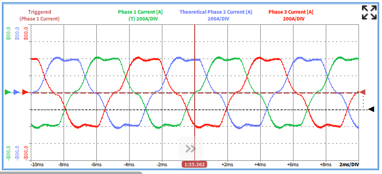
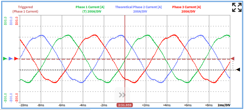
    I have noticed that the current waveforms look quite different between motoring and generating (much better in generating).

    Motoring:

    Generating:

    And if I keep increasing the current it gets even worse to the point were the inverter trips with an overcurrent.

    Any idea why you would have such a big difference between both? I believe that before I implemented the VSF the difference between the two was not so dramatic.

    One last question is related to the estimator, the function to get it running "EST_run" takes as an input value "speed_ref_pu". Does it mean that it needs to have an input speed value even if it is not running in speed control? The way I have it would take the speed reference value if running in speed control and it would take 0 if running in torque control (since there is no speed reference value). Would it make any difference is I set that value to be the current speed instead of the reference speed?

  • What's the PWM frequency and control frequency? And which current sensor are you using? The issue should be from the current sampling and control if you are using the low-side current shunt and a much lower PWM frequency than the controller.

  • The frequency of the estimator ISR is 20kHz, the PWM frequency varies from 7kHz up to 14kHz as a function of the motor speed.

    We use in-phase hall effect current sensors so I don't think that is the problem

  • 1. What do you mean motoring mode and generating mode as the figures you posted? The labs in InstaSPIN-FOC always control the machine as a motor, not consider it as the generator.  You should trigger the ADC using the estimator ISR frequency, and run all control code in estimator ISR since you are using hall effect sensors.

    2. Right, it's necessary, and will be used in some states, especially in zero speed and very low speed that will apply the force angle feature.

  • 1. Does this mean I don't really need 2 interrupts like suggested but rather just one running at higher frequency (estimator ISR at 20kHz)? At the moment, the ADC measurements are triggered by the PWM, I guess I would have to tie the ADC measurements to the estimator ISR somehow?

    2. We normally run two motors with two inverters in a back to back configuration. Normally we run one of those motors in speed mode at fixed speed and the other one in torque mode. In this case, the motor/inverter that is running in torque mode would act as motoring for Iq>0 and as generator (break) for Iq<0.

    3. Would you recommend doing something like this?:

    if (speed_mode)

    {

    EST_run(obj->estHandle,CTRL_getIab_in_addr(handle),CTRL_getVab_in_addr(handle),
    pAdcData->dcBus,TRAJ_getIntValue(obj->trajHandle_spd));

    }else{

    EST_run(obj->estHandle,CTRL_getIab_in_addr(handle),CTRL_getVab_in_addr(handle),
    pAdcData->dcBus, measured_speed);

    }

  • 1. Right if you are using hall effect sensor or inline current shunt on motor lines.

    2. That's fine, pay attention to the boosting voltage on dc bus when the Iq is set an opposite value during the motor is running.

    3. It's not critical, you just need to set a reference value according to the rotation direction, the value is only for force angle startup and identification. 

  • Does it matter when or how I trigger the ISR then (for the ADC conversion)? It used to be synced with the PWM frequency but now it will be free running at a fixed frequency. Could this pose any problem?

  • You can trigger the ADC by the using ISR timer, like CPU timer or the other PWM timers that are not for motor drive. You don't need to trigger the ADC by the PWM for motor drive since you are using an inline current sensor. So the motor is controlled by using a fixed frequency ISR always, it's not necessary to run the motor control code in two ISRs, just need to change the PWM frequency separately.

  • ok. I'll try that!

    Thanks!