This thread has been locked.

If you have a related question, please click the "Ask a related question" button in the top right corner. The newly created question will be automatically linked to this question.

TMS320F280049: The VDD decoupling capacitor is smaller than recommended value

Part Number: TMS320F280049
Other Parts Discussed in Thread: TPS560200

Hi team,

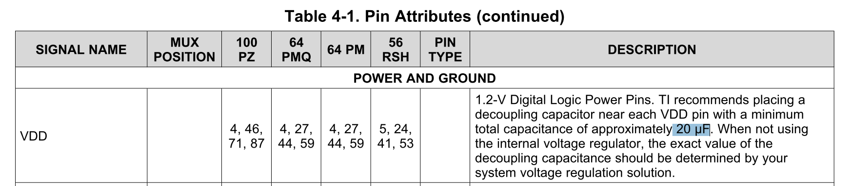
My customer found that with internal voltage regulator, the decoupling capacitance minimum value TI recommends is 20uF, however they use 4*2.2uF for long time before. They would like to know what's influence if keep using the 4*2.2uF capacitors?

What we could suggest them in this condition? Thanks!

Best Regards/Rayna

  • Hi Rayna,

    The minimum capacitance recommendation is to ensure good noise performance and stability. Are they using the LDO or the DC-DC?

  • Hi Frank,

    They use inside LDO. Each pin of VDD connects a 2.2uF capacitance.

  • Hi Frank,

    There is another issue customer met about C2000 chip went to crash and failed to reset when they tested their system with full load condition.

    They tried to find if this issue is caused by supply not stable, and tested some conditions such as connected VDD or VDDIO to ground, however the chip could reset again late.

    They would like to know what could cause the chip crash and failed to reset. Could you give some ideas or debugging methods?

    Thank you very much!

    -Rayna

  • Hi Rayna,

    It is best to always adhere to the datasheet specifications and requirements. Nevertheless, the LDO is more tolerant of insufficient capacitance compared to the DCDC. However, since they are seeing some power related issues, as a first step, I would recommend they upgrade the capacitance to meet the datasheet requirement.

    I'm not completely clear on the power issues they are facing. If they are seeing the device reset when run at full load, the likely culprit is the external supply for the 3.3v rail. Most likely the external 3.3v supply is not able to meet the current demand at full load and hence drops the voltage which resets the device. They could debug this by scoping all the rails and XRSn before and after the full load condition is entered. What external supply are they using for the 3.3v rail?

  • Hi Frank,

    Thanks for your advice!

    For the power issue, maybe i didn't make it clear for you. The issue is that the chip could not auto-reset after it crashed when run at full load. And this problem happens occasionally, not often.

    Should customer check their external supply schematic for 3.3v rail?

    Thanks!

    -Rayna

  • Rayna,

    Can you explain what you mean by the chip "crashed"?

  • Hi Frank,

    Thanks for your reply.

    The behavior of "crash issue" customer met is that EPWM goes down, relay disconnected, CAN communication with PC interface disconnected, and this happened when customer tested the PFC system during full load condition without changing anything. C2000 chip seems could not work and output anything.

    In addition, the chip could not reset by software self-checking such as watch dog reset, and have to be reset by powering up again.

    Customer has tried to debug this issue by abnormal power supply or crystal, however the above phenomenon could not be repeated, and the chip reset by itself and work again after the power signal is normal or detecting the abnormal crystal.

    What customer confused is that what could be the reason of this issue, how to debug and find the problem.

    Thanks!

    -Rayna

  • Rayna,

    Can you provide a scope capture of the rails when this "crash" condition is experienced? Please monitor the VDDIO/VDDA voltage, VDDIO/VDDA current, VDD voltage, XRSn. This should hopefully give a better idea of what's going on.

  • Hi Rayna,

    Can you reply to the previous query or if this is resolved, kindly let us know.

  • Hi Frank,

    I just got the below information, as the figures shown.

    In addition, customer mentioned that there was something not optimized with the grounding circuit near the crystal oscillator when this issue happened. However, I haven't gotten the PCB material.

    Thanks!

    Figure1 is the schematic of power supply.

    Figure2, the green part is the 3.3V power supply waveform.

    Best Regards

    -Rayna

  • Rayna,

    The regulator output is very noisy with minimum around 3v. It's possible that a current spike is dropping it low enough to trip the device because the minimum is already at 3v. They should look into cleaning up the output of the regulator because a 1v ripple is not acceptable. Taking a quick glance through TPS560200 datasheet, the nominal inductance to use is 10uH. The 33uH they are using seems much bigger. I will recommend they post on the TPS forum asking why the ripple is so high.

    Can they provide a scope shot of XRSn with the 3.3 rail? They can setup the scope to trigger on XRSn high to low transition.

  • Hi Rayna,

    Can you reply to the previous query? Or if their issue is resolved, please let us know.

  • Hi Frank, Customer didn't update useful information. I think we could close this now. thanks for your kindly help! -Rayna
  • Hi Rayna,

    No problem. Let us know if the issue crops up again.

    Regards,

    Frank