This thread has been locked.

If you have a related question, please click the "Ask a related question" button in the top right corner. The newly created question will be automatically linked to this question.

CCS/TMS320F28379D: DAC A OUTPUT UPDATE

Part Number: TMS320F28379D

Tool/software: Code Composer Studio

Good day, 

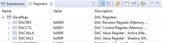
I am using the ADC SOC EPWM example in which I added DAC configuration in order to test the ADC to DAC circuit. I could verify that that the circuit works well, but the DAC output seems not to update the output once I change the ADC input. 

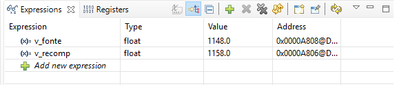
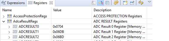
I verified that the new ADC value is updated in the Registers window. However the Expressions window keep the initial value. How do I make sure that the DAC ouput follows the ADC input ?

Please follow below the interrupt command and the windows result

interrupt void adca1_isr(void)
{

v_fonte = AdcaResultRegs.ADCRESULT0;
v_recomp = v_fonte + 10;

DAC_PTR[DAC_NUM]->DACVALS.all = v_recomp;

}

  • Hi Christian,

    What does DACVALS say in the watch window?

  • Frank, 

    Follow below the results in each windows:

    The first two tables are the initial values and the second two are the update. I clicked on pause and changed the value of the potentiometer, and pressed play again. As you can see DACVALS doesn't update.

  • Christian,

    I don't think your ADC_ISR is running. Can you place a global variable in the ADC_ISR and increment it? The variable should count up in the watch window. This way, you can be sure the ADC_ISR is running.

  • Hi Frank, 

    I didn't really understand what you asked to do. Please find below the code:

    /////TESTE ADC-TO -DAC

    float v_fonte = 0.0;
    float v_recomp = 0.0;
    //
    #define REFERENCE_VDAC 0
    #define REFERENCE_VREF 1
    #define DACA 1
    #define DACB 2
    #define DACC 3
    #define REFERENCE REFERENCE_VREF
    #define DAC_NUM DACA

    //
    // Globals
    //
    volatile struct DAC_REGS* DAC_PTR[4] = {0x0,&DacaRegs,&DacbRegs,&DaccRegs};
    Uint16 low_limit = 410;
    Uint16 high_limit = 3686;
    void configureDAC(Uint16 dac_num);

    ////// teste fim

    // Function Prototypes
    //
    void ConfigureADC(void);
    void ConfigureEPWM(void);
    void SetupADCEpwm(Uint16 channel);
    interrupt void adca1_isr(void);

    //
    // Defines
    //
    #define RESULTS_BUFFER_SIZE 256

    // Globals
    //
    Uint16 AdcaResults[RESULTS_BUFFER_SIZE];
    Uint16 resultsIndex;
    volatile Uint16 bufferFull;
    Uint16 AdcaResult0;

    void main(void)
    {
    //
    // Step 1. Initialize System Control:
    // PLL, WatchDog, enable Peripheral Clocks
    // This example function is found in the F2837xD_SysCtrl.c file.
    //
    InitSysCtrl();


    /////input xbar
    EALLOW;
    InputXbarRegs.INPUT5SELECT = 1;
    EDIS;
    ///////input xbar

    // Step 2. Initialize GPIO:
    // This example function is found in the F2837xD_Gpio.c file and
    // illustrates how to set the GPIO to it's default state.
    //
    InitGpio(); // Skipped for this example


    /////////OUTPUT X-BAR TEST ///////
    EALLOW;
    OutputXbarRegs.OUTPUT1MUX0TO15CFG.bit.MUX1 = 1;
    OutputXbarRegs.OUTPUT1MUXENABLE.bit.MUX1 = 1;
    OutputXbarRegs.OUTPUTLATCHENABLE.bit.OUTPUT1 = 0;
    OutputXbarRegs.OUTPUTINV.bit.OUTPUT1 = 0;
    EDIS;
    ////////OUTPUT X-BAR FIM //////

    //
    // Step 3. Clear all interrupts and initialize PIE vector table:
    // Disable CPU interrupts
    //
    DINT;

    //
    // Initialize the PIE control registers to their default state.
    // The default state is all PIE interrupts disabled and flags
    // are cleared.
    // This function is found in the F2837xD_PieCtrl.c file.
    //
    InitPieCtrl();

    // Disable CPU interrupts and clear all CPU interrupt flags:
    //
    IER = 0x0000;
    IFR = 0x0000;

    //
    // Initialize the PIE vector table with pointers to the shell Interrupt
    // Service Routines (ISR).
    // This will populate the entire table, even if the interrupt
    // is not used in this example. This is useful for debug purposes.
    // The shell ISR routines are found in F2837xD_DefaultIsr.c.
    // This function is found in F2837xD_PieVect.c.
    //
    InitPieVectTable();

    EINT; // Enable Global interrupt INTM
    ERTM; // Enable Global realtime interrupt DBGM
    //
    // Map ISR functions
    //
    EALLOW;
    PieVectTable.ADCA1_INT = &adca1_isr; //function for ADCA interrupt 1
    EDIS;

    //
    // Configure the ADC and power it up
    //
    ConfigureADC();

    //
    // Configure the ePWM
    //
    ConfigureEPWM();

    //
    // Setup the ADC for ePWM triggered conversions on channel 0
    //
    SetupADCEpwm(0);


    // Configure DAC
    //
    configureDAC(DAC_NUM);
    //
    // Enable global Interrupts and higher priority real-time debug events:
    //
    IER |= M_INT1; //Enable group 1 interrupts
    EINT; // Enable Global interrupt INTM
    ERTM; // Enable Global realtime interrupt DBGM

    //
    // Initialize results buffer
    //
    for(resultsIndex = 0; resultsIndex < RESULTS_BUFFER_SIZE; resultsIndex++)
    {
    AdcaResults[resultsIndex] = 0;
    }
    resultsIndex = 0;
    bufferFull = 0;

    //
    // enable PIE interrupt
    //
    PieCtrlRegs.PIEIER1.bit.INTx1 = 1;

    //
    // sync ePWM
    //
    EALLOW;
    CpuSysRegs.PCLKCR0.bit.TBCLKSYNC = 1;

    //
    //take conversions indefinitely in loop
    //
    do
    {
    //
    //start ePWM
    //
    EPwm1Regs.ETSEL.bit.SOCAEN = 1; //enable SOCA
    EPwm1Regs.TBCTL.bit.CTRMODE = 0; //unfreeze, and enter up count mode

    //
    //wait while ePWM causes ADC conversions, which then cause interrupts,
    //which fill the results buffer, eventually setting the bufferFull
    //flag
    //
    while(!bufferFull);
    bufferFull = 0; //clear the buffer full flag

    //
    //stop ePWM
    //
    EPwm1Regs.ETSEL.bit.SOCAEN = 0; //disable SOCA
    EPwm1Regs.TBCTL.bit.CTRMODE = 3; //freeze counter

    //
    //at this point, AdcaResults[] contains a sequence of conversions
    //from the selected channel
    //

    //
    //software breakpoint, hit run again to get updated conversions
    //
    asm(" ESTOP0");
    }


    while (1);

    }

    //
    // ConfigureADC - Write ADC configurations and power up the ADC for both
    // ADC A and ADC B
    //
    void ConfigureADC(void)
    {
    EALLOW;

    //
    //write configurations
    //
    AdcaRegs.ADCCTL2.bit.PRESCALE = 6; //set ADCCLK divider to /4
    AdcSetMode(ADC_ADCA, ADC_RESOLUTION_12BIT, ADC_SIGNALMODE_SINGLE);

    //
    //Set pulse positions to late
    //
    AdcaRegs.ADCCTL1.bit.INTPULSEPOS = 1;

    //
    //power up the ADC
    //
    AdcaRegs.ADCCTL1.bit.ADCPWDNZ = 1;

    //
    //delay for 1ms to allow ADC time to power up
    //
    DELAY_US(1000);

    EDIS;
    }

    //
    // ConfigureEPWM - Configure EPWM SOC and compare values
    //
    void ConfigureEPWM(void)
    {
    EALLOW;
    // Assumes ePWM clock is already enabled
    EPwm1Regs.ETSEL.bit.SOCAEN = 0; // Disable SOC on A group
    EPwm1Regs.ETSEL.bit.SOCASEL = 4; // Select SOC on up-count
    EPwm1Regs.ETPS.bit.SOCAPRD = 1; // Generate pulse on 1st event
    EPwm1Regs.CMPA.bit.CMPA = 0x0800; // Set compare A value to 2048 counts
    EPwm1Regs.TBPRD = 0x1000; // Set period to 4096 counts
    EPwm1Regs.TBCTL.bit.CTRMODE = 3; // freeze counter
    EDIS;
    }

    //
    // SetupADCEpwm - Setup ADC EPWM acquisition window
    //
    void SetupADCEpwm(Uint16 channel)
    {
    Uint16 acqps;

    //
    //determine minimum acquisition window (in SYSCLKS) based on resolution
    //
    if(ADC_RESOLUTION_12BIT == AdcaRegs.ADCCTL2.bit.RESOLUTION)
    {
    acqps = 14; //75ns
    }
    else //resolution is 16-bit
    {
    acqps = 63; //320ns
    }

    //
    //Select the channels to convert and end of conversion flag
    //
    EALLOW;
    AdcaRegs.ADCSOC0CTL.bit.CHSEL = 2; //SOC0 will convert pin A0
    AdcaRegs.ADCSOC0CTL.bit.ACQPS = acqps; //sample window is 100 SYSCLK cycles
    AdcaRegs.ADCSOC0CTL.bit.TRIGSEL = 5; //trigger on ePWM1 SOCA/C
    AdcaRegs.ADCSOC1CTL.bit.CHSEL = 2; //SOC0 will convert pin A0
    AdcaRegs.ADCSOC1CTL.bit.ACQPS = acqps; //sample window is 100 SYSCLK cycles
    AdcaRegs.ADCSOC1CTL.bit.TRIGSEL = 5; //trigger on ePWM1 SOCA/C
    AdcaRegs.ADCSOC2CTL.bit.CHSEL = 2; //SOC0 will convert pin A0
    AdcaRegs.ADCSOC2CTL.bit.ACQPS = acqps; //sample window is 100 SYSCLK cycles
    AdcaRegs.ADCSOC2CTL.bit.TRIGSEL = 5; //trigger on ePWM1 SOCA/C
    AdcaRegs.ADCINTSEL1N2.bit.INT1SEL = 0; //end of SOC0 will set INT1 flag
    AdcaRegs.ADCINTSEL1N2.bit.INT1E = 1; //enable INT1 flag
    AdcaRegs.ADCINTFLGCLR.bit.ADCINT1 = 1; //make sure INT1 flag is cleared
    EDIS;
    }

    //
    // adca1_isr - Read ADC Buffer in ISR
    //
    interrupt void adca1_isr(void)
    {

    v_fonte = AdcaResultRegs.ADCRESULT0;
    v_recomp = v_fonte + 10;

    DAC_PTR[DAC_NUM]->DACVALS.all = v_recomp ;

    }

    void configureDAC(Uint16 dac_num)
    {
    EALLOW;
    DAC_PTR[dac_num]->DACCTL.bit.DACREFSEL = REFERENCE;
    DAC_PTR[dac_num]->DACOUTEN.bit.DACOUTEN = 1;
    //
    DAC_PTR[dac_num]->DACCTL.bit.SYNCSEL = 1;
    DAC_PTR[dac_num]->DACCTL.bit.LOADMODE = 0;
    //
    DAC_PTR[dac_num]->DACVALS.all = 0;
    DELAY_US(10); // Delay for buffered DAC to power up
    EDIS;
    }
    //
    // End of file
    //

  • Christian,

    I meant increment a temp variable in your ADC ISR. Example below:

    interrupt void adca1_isr(void)
    {

    temp_variable++;

    If temp_variable keeps increasing in the watch window, that will confirm your ADC ISR is being called.

  • Hi Frank,

    I guess the ADC_ISR is not being called. As I added the global variable as follow:

    Uint16 temp_var = 0;

    in ADC_ISR,

    temp_var++;

    Unfortunately in watch window, temp_var stays at 1. 

    How can I make sure to ADC_ISR be called ?

  • Hi Frank, 

    I solved the issue. 

    Thank you 

  • Glad to hear the issue is resolved! Let us know if you ran into anymore issues.