Tool/software: Code Composer Studio
As the title, since the chip's own ram is only a few tens of k, it is necessary to use an external ram, according to the configuration of the routine. The starting address of the pointer is 0x300000, the defined length is 0xffff, and the value is 0 to increase to 0xffff.
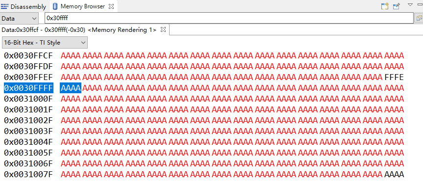
At the address 0x300000~0x30ffff, the data is correct, 0~fffe. However, the value at the address 0x30ffff is also assigned to 0~fffe. Another pointer is defined, the address bit is 0x30ffff, the length is ffff, and the address is assigned aaaa. The value of the address 0x300000~0x30ffff is also changed to aaaa. Ask a good person to help me. The results and code are as follows:
//###########################################################################
// FILE: emif1_16bit_asram.c
// TITLE: EMIF1 module accessing 16bit ASRAM.
//
//! \addtogroup cpu01_example_list
//! <h1> EMIF ASYNC module (emif1_16bit_asram)</h1>
//!
//! This example configures EMIF1 in 16bit ASYNC mode
//! This example uses CS2 as chip enable.
//!
//! \b Watch \b Variables: \n
//! - \b TEST_STATUS - Equivalent to \b TEST_PASS if test finished correctly,
//! else the value is set to \b TEST_FAIL
//! - \b ErrCount - Error counter
//!
//
//
//###########################################################################
// $TI Release: F2837xS Support Library v180 $
// $Release Date: Fri Nov 6 16:27:58 CST 2015 $
// $Copyright: Copyright (C) 2014-2015 Texas Instruments Incorporated -
// http://www.ti.com/ ALL RIGHTS RESERVED $
//###########################################################################
#include "F28x_Project.h" // Device Headerfile and Examples Include File
#define TEST_PASS 0xABCDABCD
#define TEST_FAIL 0xDEADDEAD
#define TEST_FAIL 0xDEADDEAD
Uint16 *ExRamStart = (Uint16*)0x300000;
Uint16 *Start = (Uint16*)0x30ffff;
extern void setup_emif1_pinmux_async_16bit(Uint16);
//##########EMIF1-32bit ASRAM test ######################
#define EMIF1 0
#define EMIF2 1
#define EMIF2 1
#define MEM_D_WIDTH 1 // 16Bit Memory Interface
#define TURN_AROUND_TIME 0 // Turn Around time of 2 Emif Clock
#define RD_SETUP_TIME 0 // Read Setup time of 1 Emif Clock
#define RD_STROBE_TIME 3 // Read Strobe time of 4 Emif Clock
#define RD_HOLD_TIME 0 // Read Hold time of 1 Emif Clock
#define WR_SETUP_TIME 0 // Write Hold time of 1 Emif Clock
#define WR_STROBE_TIME 0 // Write Setup time of 1 Emif Clock
#define WR_HOLD_TIME 0 // Write Hold time of 1 Emif Clock
#define EXTEND_WAIT 0 // Disable Extended Wait
#define STROBE_SEL 0 // Disable Strobe Mode.
#define WAIT_POLAR_INV 0
#define WAIT_COUNT 0
Uint16 ErrCount = 0;
Uint32 TEST_STATUS;
int i;
void main(void)
{
// char ErrCount_local;
//TEST_STATUS = TEST_FAIL;
InitSysCtrl();
DINT;
// Initialize the PIE control registers to their default state.
// The default state is all PIE interrupts disabled and flags
// are cleared.
// This function is found in the F2837xS_PieCtrl.c file.
InitPieCtrl();
// Initialize the PIE control registers to their default state.
// The default state is all PIE interrupts disabled and flags
// are cleared.
// This function is found in the F2837xS_PieCtrl.c file.
InitPieCtrl();
// Disable CPU interrupts and clear all CPU interrupt flags:
EALLOW;
IER = 0x0000;
IFR = 0x0000;
EDIS;
// Initialize the PIE vector table with pointers to the shell Interrupt
// GService Routines (ISR).
// This will populate the entire table, even if the interrupt
// is not used in this example. This is useful for debug purposes.
// The shell ISR routines are found in F2837xS_DefaultIsr.c.
// This function is found in F2837xS_PieVect.c.
InitPieVectTable();
//Configure to run EMIF1 on full Rate (EMIF1CLK = CPU1SYSCLK)
EALLOW;
ClkCfgRegs.PERCLKDIVSEL.bit.EMIF1CLKDIV = 0x0;
EDIS;
EALLOW;
ClkCfgRegs.PERCLKDIVSEL.bit.EMIF1CLKDIV = 0x0;
EDIS;
EALLOW;
//Disable Access Protection (CPU_FETCH/CPU_WR/DMA_WR)
Emif1ConfigRegs.EMIF1ACCPROT0.all = 0x0;
if (Emif1ConfigRegs.EMIF1ACCPROT0.all != 0x0)
{
ErrCount++;
}
Emif1ConfigRegs.EMIF1ACCPROT0.all = 0x0;
if (Emif1ConfigRegs.EMIF1ACCPROT0.all != 0x0)
{
ErrCount++;
}
// Commit the configuration related to protection. Till this bit remains set
// content of EMIF1ACCPROT0 register can't be changed.
Emif1ConfigRegs.EMIF1COMMIT.all = 0x1;
if(Emif1ConfigRegs.EMIF1COMMIT.all != 0x1)
{
ErrCount++;
}
// content of EMIF1ACCPROT0 register can't be changed.
Emif1ConfigRegs.EMIF1COMMIT.all = 0x1;
if(Emif1ConfigRegs.EMIF1COMMIT.all != 0x1)
{
ErrCount++;
}
// Lock the configuration so that EMIF1COMMIT register can't be changed any more.
Emif1ConfigRegs.EMIF1LOCK.all = 0x1;
if (Emif1ConfigRegs.EMIF1LOCK.all != 1)
{
ErrCount++;
}
Emif1ConfigRegs.EMIF1LOCK.all = 0x1;
if (Emif1ConfigRegs.EMIF1LOCK.all != 1)
{
ErrCount++;
}
EDIS;
//Configure GPIO pins for EMIF1
setup_emif1_pinmux_async_16bit(0);
setup_emif1_pinmux_async_16bit(0);
//////////////////////////////////////////////
Uint32 i=0;
for(i = 0; i< 0xFFFF; i++)
{
*(ExRamStart + i) = i;
}
asm(" ESTOP0");
for(i=0;i<0xffff;i++){
*(Start + i) = 0xaaaa;
}
asm(" ESTOP0");
// asm(" ESTOP0");
while (1);
}