


I am working on a project where I am ultimately trying to generate 8 PWM signals at a high frequency. To accomplish this I have been using some heavily modified example code and the complementary ePWM pins. Lately I have been running into an issue where ePWM signals will stop generating under certain conditions.
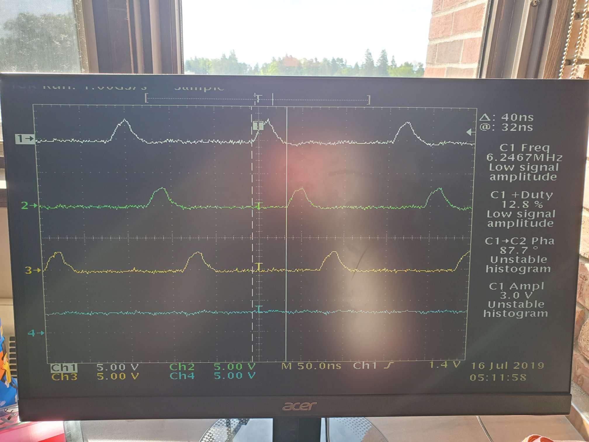
In my code, I have ePWM1 as the master module and am adjusting the phase for ePWM(2-5). At 12.5% duty cycle, if I set the phase past 315 degrees (PhaseReg[x] >=21) the signal just disappears. I have also observed that when the signals are shifted 270 degrees (PhaseReg[x] =18), if I set DutyCycle = 6 -- (50%), the same will happen. The only exception for both cases is ePWM2 which seems to work regardless.
Is there something different about ePWM2 that allows more modification, or is there something in my code that is restricting the usage of the other ePWM signals?
I am including two photos: one with all signals as I want and one when I adjust the phase value and channel 4 disappears.

//###########################################################################
//
// FILE:    Example_2833xHRPWM_Symmetric_Duty_Cycle_SFO_V5.c
//
// TITLE:   High Resolution PWM Symmetric Duty Cycle SFO V5 Example
//
//! \addtogroup f2833x_example_list
//! <h1>High Resolution PWM Symmetric Duty Cycle SFO V5</h1>
//!
//! This example modifies the MEP control registers to show symmetric edge
//! displacement due to the HRPWM control extension of the respective ePWM
//! module.
//!
//! \note By default, this example project is configured for floating-point
//!  math. All included libraries must be pre-compiled for floating-point math.
//! Therefore, SFO_TI_Build_V5B_fpu.lib (compiled for floating-point) is
//! included in the project instead of the SFO_TI_Build_V5B.lib
//!  (compiled for fixed-point).
//! To convert the example for fixed-point math, follow the instructions in
//! sfo_readme.txt in the /doc directory of the header files and peripheral
//! examples package.
//!
//! \note This program requires the DSP2833x header files, which include
//! the following files required for this example:
//! SFO_V5.h and SFO_TI_Build_V5B_fpu.lib (or SFO_TI_Build_V5B.lib for
//! fixed point)
//!
//! This example calls the following TI's MEP Scale Factor Optimizer (SFO)
//! software library V5 functions:
//!
//! - \b int \b SFO_MepDis_V5(int i);   updates MEP_ScaleFactor[i] when HRPWM
//!   is not used
//! - \b Returns
//!     - 1 when complete for the specified channel
//!     - 0 if not complete for the specified channel
//!
//!
//! Channel ePWM1A will have fine edge movement due to the HRPWM logic when the
//! duty cycle is altered. \n
//! Channel ePWM1B has a fixed 50% duty cycle.
//!
//! - 5MHz PWM (for 150 MHz SYSCLKOUT), ePWM1A toggle high/low with MEP control
//!   on rising edge
//! - 3.33MHz PWM (for 100 MHz SYSCLKOUT), ePWM1A toggle high/low with MEP
//!   control on rising edge
//!
//! \b Running \b the \b Application \n
//! -# \b **!!IMPORTANT!!** - in SFO_V5.h, set PWM_CH to the max number of
//! HRPWM channels plus one. For example, for the F28335, the
//! maximum number of HRPWM channels is 6. 6+1=7, so set
//! \#define PWM_CH 7 in SFO_V5.h. (Default is 7)
//! -# Run this example at 150/100MHz SYSCLKOUT
//! -# Watch ePWM1 waveforms on a Oscilloscope
//!
//! \b External \b Connections \n
//! Monitor the following pins on an oscilloscope:
//! - ePWM1A is on GPIO0
//! - ePWM1B is on GPIO1
//!
//! \b Watch \b Variables \n
//! - MEP_ScaleFactor
//! - EPwm1Regs.CMPA.all
//! - EPwm1Regs.CMPB.all
//!
//
//###########################################################################
// $TI Release: F2833x Support Library v2.00.00.00 $
// $Release Date: Mon May 27 06:46:54 CDT 2019 $
// $Copyright:
// Copyright (C) 2009-2019 Texas Instruments Incorporated - http://www.ti.com/
//
// Redistribution and use in source and binary forms, with or without
// modification, are permitted provided that the following conditions
// are met:
//
//   Redistributions of source code must retain the above copyright
//   notice, this list of conditions and the following disclaimer.
//
//   Redistributions in binary form must reproduce the above copyright
//   notice, this list of conditions and the following disclaimer in the
//   documentation and/or other materials provided with the
//   distribution.
//
//   Neither the name of Texas Instruments Incorporated nor the names of
//   its contributors may be used to endorse or promote products derived
//   from this software without specific prior written permission.
//
// THIS SOFTWARE IS PROVIDED BY THE COPYRIGHT HOLDERS AND CONTRIBUTORS
// "AS IS" AND ANY EXPRESS OR IMPLIED WARRANTIES, INCLUDING, BUT NOT
// LIMITED TO, THE IMPLIED WARRANTIES OF MERCHANTABILITY AND FITNESS FOR
// A PARTICULAR PURPOSE ARE DISCLAIMED. IN NO EVENT SHALL THE COPYRIGHT
// OWNER OR CONTRIBUTORS BE LIABLE FOR ANY DIRECT, INDIRECT, INCIDENTAL,
// SPECIAL, EXEMPLARY, OR CONSEQUENTIAL DAMAGES (INCLUDING, BUT NOT
// LIMITED TO, PROCUREMENT OF SUBSTITUTE GOODS OR SERVICES; LOSS OF USE,
// DATA, OR PROFITS; OR BUSINESS INTERRUPTION) HOWEVER CAUSED AND ON ANY
// THEORY OF LIABILITY, WHETHER IN CONTRACT, STRICT LIABILITY, OR TORT
// (INCLUDING NEGLIGENCE OR OTHERWISE) ARISING IN ANY WAY OUT OF THE USE
// OF THIS SOFTWARE, EVEN IF ADVISED OF THE POSSIBILITY OF SUCH DAMAGE.
// $
//###########################################################################

//
// Included Files
//
#include "DSP28x_Project.h"     // Device Headerfile and Examples Include File
#include "DSP2833x_EPwm_defines.h"  // useful defines for initialization
#include "DSP2833x_Examples.h"
//
// SFO V5 library headerfile - required to use SFO library functions
//
#include "SFO_V5.h"
void Setup_ePWM(void);
//
//                              !!IMPORTANT!!
// UPDATE NUMBER OF HRPWM CHANNELS + 1  USED IN SFO_V5.H
// i.e. #define PWM_CH     // F28335 has a maximum of 6 HRPWM channels (7=6+1)
//
////////////////////////////////////////////////////////////////////////////////////////////////////////////new stuff


////////////////////////////////////////////////////////////////////////////////////////////////////////


//
// Function Prototypes
//
void HRPWM1_Config(int);
//void HRPWM2_Config(int);
//void HRPWM3_Config(int);
//void HRPWM4_Config(int);
//void HRPWM5_Config(int);
//void HRPWM6_Config(int);

void HRPWM33_Config(int);

void error (void);
__interrupt void FreqCtlISR(void);  // frequency modulation & phase sync ISR

//
// General System variables - useful for debug
//
Uint16 status;
Uint16 CMP_Reg = 20;
Uint16 CMP_HR = 0;
Uint16 PRD_Reg = 40;
Uint16 PRD_HR = 0;
Uint16 update = 0;
Uint16 isr_cnt = 0;
Uint16 change_dir = 1;
Uint16 update_rate = 10000;
Uint16 CMP_Inc = 0;
Uint16 CMP_HR_INC = 0;
Uint32 InputCMPInc = 2621;
int32 CMP_HR_temp = 0;
//Uint16 Period = 50;
int16 CMPA_reg_val=0;
int16 CMPAHR_reg_val=0;

//
// The following declarations are required in order to use the SFO
// library functions:
//

//
// Global array used by the SFO library
// For n HRPWM channels + 1 for MEP_ScaleFactor[0]
//
int MEP_ScaleFactor[PWM_CH];

//
// Array of pointers to EPwm register structures:
// *ePWM[0] is defined as dummy value not used in the example
//
volatile struct EPWM_REGS *ePWM[PWM_CH] =
             {  &EPwm1Regs, &EPwm1Regs, &EPwm2Regs, &EPwm3Regs,
                &EPwm4Regs, &EPwm5Regs, &EPwm6Regs};


//
// Main
//
//Defined Values
//
    Uint16 Period = 12;
    Uint16 DutyCycle = 3; //(DutyCycle/Period)/2 = %
    Uint16 PhaseReg2 = 0; //Keep at 0. This is acting as the base signal
    Uint16 PhaseReg3 = 6;  //| 50%  Period
    Uint16 PhaseReg4 = 12; //| 100% Period - Phases should evenly divide into 2*Period for 90 degree shift (45 degree w/ complementary)
    Uint16 PhaseReg5 = 21; //| 150% Period

void main(void)
 {
    int i;

    //
    // Step 1. Initialize System Control:
    // PLL, WatchDog, enable Peripheral Clocks
    // This example function is found in the DSP2833x_SysCtrl.c file.
    //
    InitSysCtrl();

    //
    // Step 2. Initialize GPIO:
    // This example function is found in the DSP2833x_Gpio.c file and
    // illustrates how to set the GPIO to it's default state.
    //
    // InitGpio();  // Skipped for this example

    //
    // For this case just init GPIO pins for ePWM1-ePWM6
    // This function is in the DSP2833x_EPwm.c file
    //
    InitEPwmGpio();

    //
    // Step 3. Clear all interrupts and initialize PIE vector table:
    // Disable CPU interrupts
    //
    DINT;

    //
    // Initialize the PIE control registers to their default state.
    // The default state is all PIE interrupts disabled and flags
    // are cleared.
    // This function is found in the DSP2833x_PieCtrl.c file.
    //
    InitPieCtrl();

    //
    // Disable CPU interrupts and clear all CPU interrupt flags
    //
    IER = 0x0000;
    IFR = 0x0000;

    //
    // Initialize the PIE vector table with pointers to the shell Interrupt
    // Service Routines (ISR).
    // This will populate the entire table, even if the interrupt
    // is not used in this example.  This is useful for debug purposes.
    // The shell ISR routines are found in DSP2833x_DefaultIsr.c.
    // This function is found in DSP2833x_PieVect.c.
    //
    InitPieVectTable();

    EALLOW;
    PieVectTable.EPWM1_INT = &FreqCtlISR;
    EDIS;

    //
    // Step 4. Initialize all the Device Peripherals:
    // This function is found in DSP2833x_InitPeripherals.c
    //
    // InitPeripherals();  // Not required for this example

    EALLOW;
    SysCtrlRegs.PCLKCR0.bit.TBCLKSYNC = 0;
    EDIS;

    //
    // MEP_ScaleFactor variables initialization for SFO library functions
    //
    for(i=0;i<PWM_CH;i++)
    {
        MEP_ScaleFactor[i] =0;
    }

    //
    // MEP_ScaleFactor variables initialization using SFO_MepDis_V5 library
    // function.
    //
    EALLOW;
    for(i=1;i<PWM_CH;i++)
    {
        //
        // Enable HRPWM logic for channel prior to calibration
        //
        (*ePWM[i]).HRCNFG.bit.EDGMODE = 1;

        //
        // returns "0" when cal. incomplete for channel
        //
        while ( SFO_MepDis_V5(i) == SFO_INCOMPLETE );
        {

        }
    }
    EDIS;

    //
    // Initialize a common seed variable MEP_ScaleFactor[0] required for all
    // SFO functions
    //
    MEP_ScaleFactor[0] = MEP_ScaleFactor[1];

    //
    //  Some useful Period vs Frequency values
    //  SYSCLKOUT =     150MHz         100 MHz
    //  -----------------------------------------
    //  Period          Frequency      Frequency
    //  1000            150 kHz        100 KHz
    //  800             187 kHz        125 KHz
    //  600             250 kHz        167 KHz
    //  500             300 kHz        200 KHz
    //  250             600 kHz        400 KHz
    //  200             750 kHz        500 KHz
    //  100             1.5 MHz        1.0 MHz
    //  50              3.0 MHz        2.0 MHz
    //  25              6.0 MHz        4.0 MHz
    //  20              7.5 MHz        5.0 MHz
    //  12              12.5 MHz       8.33 MHz
    //  10              15.0 MHz       10.0 MHz
    //  9               16.7 MHz       11.1 MHz
    //  8               18.8 MHz       12.5 MHz
    //  7               21.4 MHz       14.3 MHz
    //  6               25.0 MHz       16.7 MHz
    //  5               30.0 MHz       20.0 MHz
    //

    //
    // ePWM and HRPWM register initialization
    //

    //
    // ePWMx target, 5 MHz PWM(150MHz SYSCLKOUT)/3.33 MHz PWM(100MHz SYSCLKOUT)
    //
    HRPWM1_Config(Period);
//    HRPWM2_Config(15);
//    HRPWM3_Config(15);
//    HRPWM4_Config(15);
//    HRPWM5_Config(15);
//    HRPWM6_Config(15);


    EALLOW;
    SysCtrlRegs.PCLKCR0.bit.TBCLKSYNC = 1;
    EDIS;

    //
    // configure ePWM1 to generate interrupts on period match
    //
    EPwm1Regs.ETSEL.bit.INTSEL = 1;     // interrupt on counter zero match
    EPwm1Regs.ETSEL.bit.INTEN = 1;      // enable peripheral interrupt
    EPwm1Regs.ETPS.bit.INTPRD = 1;      // generate interrupt on every event
    PieCtrlRegs.PIEIER3.bit.INTx1 = 1;  // enable ePWM1 interrupt in PIE
    IER |= 0x0004;                      // enable core INT #3
    EINT;                               // clear global interrupt mask

    for(;;)
    {
        if (isr_cnt >= update_rate)
        {
            if (CMP_Reg < (PRD_Reg-4) && change_dir == 1)   // Increment CMP
            {
                CMP_Inc = InputCMPInc >> 16;
                CMP_HR_INC = (Uint16) InputCMPInc;
                CMP_Reg = CMP_Reg+CMP_Inc;
                CMP_HR_temp = (Uint32)CMP_HR + (Uint32)CMP_HR_INC;

                if(CMP_HR_temp>=0x10000)
                {
                    CMP_HR_temp = CMP_HR_temp-0x10000;
                    CMP_Reg = CMP_Reg;//+1;
                }

                CMP_HR = (Uint16) CMP_HR_temp;
            }

            else
            {
                change_dir = 0;                             // Decrement CMP
            }

            if (CMP_Reg > 4 && change_dir == 0) // Decrement CMP
            {
                CMP_Inc = InputCMPInc >> 16;
                CMP_HR_INC = (Uint16) InputCMPInc;
                CMP_Reg = CMP_Reg-CMP_Inc;
                CMP_HR_temp = (int32)CMP_HR - (int32)CMP_HR_INC;

                if(CMP_HR_temp < 0)
                {
                    CMP_HR_temp = 0x10000 + CMP_HR_temp;
                    CMP_Reg = CMP_Reg-1;
                }
                CMP_HR = (Uint16) CMP_HR_temp;
            }

            else
            {
                change_dir = 1;                             // Increment CMP
            }
            update = 1;
            isr_cnt = 0;
        }
    }
}

//
// HRPWM_Config - Configures all ePWM channels and sets up HRPWM on ePWMxA
// channels
//

void HRPWM1_Config(period)
{
    // EPWM Module 1 config ------Only used as master module to set phase for other EPWM (2-5)
    EPwm1Regs.TBPRD = period; // Period = # TBCLK counts
    EPwm1Regs.TBPHS.half.TBPHS = 0; // Set Phase register
    EPwm1Regs.TBCTL.bit.CTRMODE = TB_COUNT_UPDOWN; // Symmetrical mode
    EPwm1Regs.TBCTL.bit.PHSEN = 1;//TB_DISABLE; // Master module
    EPwm1Regs.TBCTL.bit.PRDLD = TB_SHADOW;
    EPwm1Regs.TBCTL.bit.SYNCOSEL = 1;//TB_CTR_ZERO; // Sync down-stream module

    EPwm1Regs.TBCTL.bit.HSPCLKDIV = TB_DIV1;
    EPwm1Regs.TBCTL.bit.CLKDIV = TB_DIV1;
    EPwm1Regs.TBCTL.bit.FREE_SOFT = 0x3;

    EPwm1Regs.CMPCTL.bit.SHDWAMODE = CC_SHADOW;
    EPwm1Regs.CMPCTL.bit.SHDWBMODE = CC_SHADOW;
    EPwm1Regs.CMPCTL.bit.LOADAMODE = CC_CTR_ZERO; // load on CTR=Zero
    EPwm1Regs.CMPCTL.bit.LOADBMODE = CC_CTR_ZERO; // load on CTR=Zero

    EPwm1Regs.AQCTLA.bit.ZRO = AQ_SET; // set actions for EPWM1A
    EPwm1Regs.AQCTLA.bit.CAU = AQ_CLEAR;
    EPwm1Regs.AQCTLB.bit.ZRO = AQ_CLEAR; // set actions for EPWM1B
    EPwm1Regs.AQCTLB.bit.CAD = AQ_SET;

    // EPWM Module 2 config
    EPwm2Regs.TBPRD = period; // Period = # TBCLK counts
    EPwm2Regs.TBPHS.half.TBPHS = PhaseReg2; // Set Phase register
    EPwm2Regs.TBCTL.bit.CTRMODE = TB_COUNT_UPDOWN; // Symmetrical mode
    EPwm2Regs.TBCTL.bit.PHSEN = TB_ENABLE; // Slave module
    EPwm2Regs.TBCTL.bit.PRDLD = TB_SHADOW;
    EPwm2Regs.TBCTL.bit.SYNCOSEL = 0;//TB_SYNC_IN; // sync flow-through

    EPwm2Regs.TBCTL.bit.HSPCLKDIV = TB_DIV1;
    EPwm2Regs.TBCTL.bit.CLKDIV = TB_DIV1;
    EPwm2Regs.TBCTL.bit.FREE_SOFT = 0x3;

    EPwm2Regs.CMPCTL.bit.SHDWAMODE = CC_SHADOW;
    EPwm2Regs.CMPCTL.bit.SHDWBMODE = CC_SHADOW;
    EPwm2Regs.CMPCTL.bit.LOADAMODE = CC_CTR_ZERO; // load on CTR=Zero
    EPwm2Regs.CMPCTL.bit.LOADBMODE = CC_CTR_ZERO; // load on CTR=Zero

    EPwm2Regs.AQCTLA.bit.ZRO = AQ_SET; // set actions for EPWM1A
    EPwm2Regs.AQCTLA.bit.CAU = AQ_CLEAR;
    EPwm2Regs.AQCTLB.bit.ZRO = AQ_CLEAR; // set actions for EPWM1B
    EPwm2Regs.AQCTLB.bit.CAD = AQ_SET;

    // EPWM Module 3 config
    EPwm3Regs.TBPRD = period; // Period = # TBCLK counts
    EPwm3Regs.TBPHS.half.TBPHS = PhaseReg3; // Set Phase register
    EPwm3Regs.TBCTL.bit.CTRMODE = TB_COUNT_UPDOWN; // Symmetrical mode
    EPwm3Regs.TBCTL.bit.PHSEN = TB_ENABLE; // Slave module
    EPwm3Regs.TBCTL.bit.PRDLD = TB_SHADOW;
    EPwm3Regs.TBCTL.bit.SYNCOSEL = 0;//TB_SYNC_IN; // sync flow-through

    EPwm3Regs.TBCTL.bit.HSPCLKDIV = TB_DIV1;
    EPwm3Regs.TBCTL.bit.CLKDIV = TB_DIV1;
    EPwm3Regs.TBCTL.bit.FREE_SOFT = 0x3;

    EPwm3Regs.CMPCTL.bit.SHDWAMODE = CC_SHADOW;
    EPwm3Regs.CMPCTL.bit.SHDWBMODE = CC_SHADOW;
    EPwm3Regs.CMPCTL.bit.LOADAMODE = CC_CTR_ZERO; // load on CTR=Zero
    EPwm3Regs.CMPCTL.bit.LOADBMODE = CC_CTR_ZERO; // load on CTR=Zero

    EPwm3Regs.AQCTLA.bit.ZRO = AQ_SET; // set actions for EPWM1A
    EPwm3Regs.AQCTLA.bit.CAU = AQ_CLEAR;
    EPwm3Regs.AQCTLB.bit.ZRO = AQ_CLEAR; // set actions for EPWM1B
    EPwm3Regs.AQCTLB.bit.CAD = AQ_SET;

    // EPWM Module 4 config
    EPwm4Regs.TBPRD = period; // Period = # TBCLK counts
    EPwm4Regs.TBPHS.half.TBPHS = PhaseReg4; // Set Phase register
    EPwm4Regs.TBCTL.bit.CTRMODE = TB_COUNT_UPDOWN; // Symmetrical mode
    EPwm4Regs.TBCTL.bit.PHSEN = TB_ENABLE; // Slave module
    EPwm4Regs.TBCTL.bit.PRDLD = TB_SHADOW;
    EPwm4Regs.TBCTL.bit.SYNCOSEL = 0;//TB_SYNC_IN; // sync flow-through

    EPwm4Regs.TBCTL.bit.HSPCLKDIV = TB_DIV1;
    EPwm4Regs.TBCTL.bit.CLKDIV = TB_DIV1;
    EPwm4Regs.TBCTL.bit.FREE_SOFT = 0x3;

    EPwm4Regs.CMPCTL.bit.SHDWAMODE = CC_SHADOW;
    EPwm4Regs.CMPCTL.bit.SHDWBMODE = CC_SHADOW;
    EPwm4Regs.CMPCTL.bit.LOADAMODE = CC_CTR_ZERO; // load on CTR=Zero
    EPwm4Regs.CMPCTL.bit.LOADBMODE = CC_CTR_ZERO; // load on CTR=Zero

    EPwm4Regs.AQCTLA.bit.ZRO = AQ_SET; // set actions for EPWM1A
    EPwm4Regs.AQCTLA.bit.CAU = AQ_CLEAR;
    EPwm4Regs.AQCTLB.bit.ZRO = AQ_CLEAR; // set actions for EPWM1B
    EPwm4Regs.AQCTLB.bit.CAD = AQ_SET;

    // EPWM Module 4 config
    EPwm5Regs.TBPRD = period; // Period = # TBCLK counts
    EPwm5Regs.TBPHS.half.TBPHS = PhaseReg5; // Set Phase register
    EPwm5Regs.TBCTL.bit.CTRMODE = TB_COUNT_UPDOWN; // Symmetrical mode
    EPwm5Regs.TBCTL.bit.PHSEN = TB_ENABLE; // Slave module
    EPwm5Regs.TBCTL.bit.PRDLD = TB_SHADOW;
    EPwm5Regs.TBCTL.bit.SYNCOSEL = 0;//TB_SYNC_IN; // sync flow-through

    EPwm5Regs.TBCTL.bit.HSPCLKDIV = TB_DIV1;
    EPwm5Regs.TBCTL.bit.CLKDIV = TB_DIV1;
    EPwm5Regs.TBCTL.bit.FREE_SOFT = 0x3;

    EPwm5Regs.CMPCTL.bit.SHDWAMODE = CC_SHADOW;
    EPwm5Regs.CMPCTL.bit.SHDWBMODE = CC_SHADOW;
    EPwm5Regs.CMPCTL.bit.LOADAMODE = CC_CTR_ZERO; // load on CTR=Zero
    EPwm5Regs.CMPCTL.bit.LOADBMODE = CC_CTR_ZERO; // load on CTR=Zero

    EPwm5Regs.AQCTLA.bit.ZRO = AQ_SET; // set actions for EPWM1A
    EPwm5Regs.AQCTLA.bit.CAU = AQ_CLEAR;
    EPwm5Regs.AQCTLB.bit.ZRO = AQ_CLEAR; // set actions for EPWM1B
    EPwm5Regs.AQCTLB.bit.CAD = AQ_SET;
    //============================================================
    EPwm1Regs.CMPA.half.CMPA = 0; // adjust duty for output EPWM1A & EPWM1B
//    EPwm1Regs.CMPB = 7; // adjust point-in-time for ADCSOC trigger
    EPwm2Regs.CMPA.half.CMPA = DutyCycle; // adjust duty for output EPWM2A & EPWM2B ----
//    EPwm2Regs.CMPB = 12; // adjust point-in-time for ADCSOC trigger
    EPwm3Regs.CMPA.half.CMPA = DutyCycle; // adjust duty for output EPWM3A & EPWM3B
//    EPwm3Regs.CMPB = 12; // adjust point-in-time for ADCSOC trigger
    EPwm4Regs.CMPA.half.CMPA = DutyCycle; // adjust duty for output EPWM4A & EPWM4B
//    EPwm4Regs.CMPB = 100; // adjust point-in-time for ADCSOC trigger
    EPwm5Regs.CMPA.half.CMPA = DutyCycle; // adjust duty for output EPWM5A & EPWM5B
//    EPwm5Regs.CMPB = 12; // adjust point-in-time for ADCSOC trigger

}

//
// FreqCtlISR - interrupts at ePWM1 TBCTR = 0. This ISR updates the compare and
// period registers for ePWM modules within the same period.
//

__interrupt void
FreqCtlISR(void)
{
    EALLOW;
    EPwm2Regs.TBCTL.bit.PHSEN = 0;
    EDIS;

    isr_cnt++;

    if (update == 1)
    {
        EPwm1Regs.CMPA.half.CMPA = CMP_Reg;
        CMPAHR_reg_val = (CMP_HR*MEP_ScaleFactor[1])>>15;
        CMPAHR_reg_val = CMPAHR_reg_val << 8;
        CMPAHR_reg_val += 0x0180;
        EPwm1Regs.CMPA.half.CMPAHR = CMPAHR_reg_val;
        update = 0;
    }

    //
    // re-initialise for next PWM interrupt
    //
    PieCtrlRegs.PIEACK.all = PIEACK_GROUP3;  // acknowledge PIE interrupt
    EPwm1Regs.ETCLR.bit.INT = 1;             // clear interrupt bit
}

//
// error - An error occurs when the MEP_ScaleFactor [n] calculated from
// SFO_MEPEn_V5 differs by > +/- 15 from the Seed Value in MEP_ScaleFactor[0].
// SFO_MepEn_V5 returned a "2" (SFO_OUTRANGE_ERROR). The user should:
// (1) Re-run SFO_MepDis_V5 to re-calibrate an appropriate seed value.
// (2) Ensure the code is not calling Mep_En_V5 on a different channel when it
//     is currently still running on a channel. (Repetitively call Mep_En_V5 on
//     current channel until an SFO_COMPLETE ( i.e. 1) is returned.
// (3) If the out-of-range condition is acceptable for the application, ignore
//     the "2" and treat it as a "1" or SFO_COMPLETE.
//
void
error (void)
{
    //
    // Error - MEP_ScaleFactor out of range of Seed - rerun MepDis calibration.
    //
    ESTOP0;
}

//
// End of File
//
