This thread has been locked.

If you have a related question, please click the "Ask a related question" button in the top right corner. The newly created question will be automatically linked to this question.

CCS/TMS320F280049: ADC Trigger from multiple EPWM points

Part Number: TMS320F280049

Tool/software: Code Composer Studio

Hello I would like to trigger ADC1 two time during one period (as shown in the picture).

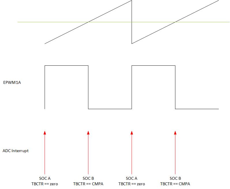
I tried this with SOCA and SOCB, but the ADC Interrupt occurs only at the first one. Both SOC A/B are working separately but not together.

  • Hi,

    Can you check if duration between SOCA and SOCB generation is sufficient enough for a conversion to complete?

    Thanks

    Vasudha

  • Hello,

    yes, this is possible. I tried my problem with two interrupt handler and it is working. If I choose the same interrupt handler it is not working.

    I added my code to this message.

    #include "driverlib.h"
    #include "device.h"
    //#include "F28x_Project.h"
    #include "main.h"
    
    //
    // Defines
    //
    
    #define EPWM1_TIMER_TBPRD               1000U
    #define EPWM1_CMPA                      500U
    #define EPWM_CMP_UP                     1U
    #define EPWM_CMP_DOWN                   0U
    
    //Define Outputs
    #define DEVICE_GPIO_PIN_DRIVER1         10U
    #define DEVICE_GPIO_PIN_DRIVER2         11U
    #define DEVICE_GPIO_PIN_ANALOGCONT      12U
    #define DEVICE_GPIO_PIN_COMPROGDIS      13U
    #define DEVICE_GPIO_PIN_COMPSHUNTDIS    17U
    
    //Define Inputs
    #define DEVICE_GPIO_PIN_PWMCONTSHUNT    16U
    #define DEVICE_GPIO_PIN_PWMCONTROG      6U
    
    //
    // Defines
    //
    #define RESULTS_BUFFER_SIZE     256
    
    //
    // Globals
    //
    uint16_t adcAResults[RESULTS_BUFFER_SIZE];
    uint16_t adcAResults2[RESULTS_BUFFER_SIZE];   // Buffer for results
    uint16_t adcAResults3[RESULTS_BUFFER_SIZE];
    uint16_t index;                              // Index into result buffer
    volatile uint16_t bufferFull;                // Flag to indicate buffer is full


    void initEPWM1(void);
    void initADC(void);
    void initADCSOC(void);
    __interrupt void adcA1ISR(void);
    
    
    void main(void)
     {
    
    
        // Initialize device clock and peripherals
        //Initialize external Crystal (Technical manuel p. 100):
        Device_init();
    
        // Initialize GPIO and configure the GPIO pin as a push-pull output
        Device_initGPIO();
    
    
    	GPIO_setPadConfig(24U, GPIO_PIN_TYPE_STD);
        GPIO_setDirectionMode(24U, GPIO_DIR_MODE_OUT);
    	
        //Initialize PWM
        GPIO_setPadConfig(0U, GPIO_PIN_TYPE_STD);
        GPIO_setPinConfig(GPIO_0_EPWM1A);
    
        //
        // Initialize PIE and clear PIE registers. Disables CPU interrupts.
        //
    
        Interrupt_initModule();
    
        //
        // Initialize the PIE vector table with pointers to the shell Interrupt
        // Service Routines (ISR).
        //
        Interrupt_initVectorTable();
        // Enable Global Interrupt (INTM) and realtime interrupt (DBGM)
    
        //
        // Initialize the PIE vector table with pointers to the shell Interrupt
        // Service Routines (ISR).
        //
        Interrupt_register(INT_ADCA1, &adcA1ISR);
    
        //init ADC and power it up; init EPWM
        initADC();
    
        //
        // Disable sync(Freeze clock to PWM as well)
        //
        SysCtl_disablePeripheral(SYSCTL_PERIPH_CLK_TBCLKSYNC);
    
    
        initEPWM1();
    
        //
        // Enable sync and clock to PWM
        //
    
        SysCtl_enablePeripheral(SYSCTL_PERIPH_CLK_TBCLKSYNC);
    
    
        initADCSOC();
    
        for(index = 0; index < RESULTS_BUFFER_SIZE; index++)
        {
            adcAResults[index] = 0;
            adcAResults2[index] = 0;
            adcAResults3[index] = 0;
        }
    
        index = 0;
        bufferFull = 0;
    
        //
        // Enable ADC interrupt
        //
        Interrupt_enable(INT_ADCA1);
    
    
        EINT;
        ERTM;


        EPWM_enableADCTrigger(EPWM1_BASE, EPWM_SOC_A);
        EPWM_enableADCTrigger(EPWM1_BASE, EPWM_SOC_B);
        EPWM_setTimeBaseCounterMode(EPWM1_BASE, EPWM_COUNTER_MODE_UP);
    
        // Loop Forever
        for(;;)
        {
    
            while(bufferFull == 0)
           {
           }
           bufferFull = 0;     // Clear the buffer full flag
    
        }
    }
    
    void initEPWM1()
    {
        //
        // Disable SOCA
        //
       EPWM_disableADCTrigger(EPWM1_BASE, EPWM_SOC_A);
       EPWM_disableADCTrigger(EPWM1_BASE, EPWM_SOC_B);
        //
        // Configure the SOC to occur on the first up-count event
        //
       EPWM_setADCTriggerSource(EPWM1_BASE, EPWM_SOC_A, EPWM_SOC_TBCTR_U_CMPA);
       EPWM_setADCTriggerSource(EPWM1_BASE, EPWM_SOC_B, EPWM_SOC_TBCTR_ZERO);
       EPWM_setADCTriggerEventPrescale(EPWM1_BASE, EPWM_SOC_A, 1);
       EPWM_setADCTriggerEventPrescale(EPWM1_BASE, EPWM_SOC_B, 1);
    
    
        //
        // Set-up TBCLK
        //
        EPWM_setTimeBasePeriod(EPWM1_BASE, EPWM1_TIMER_TBPRD);
        EPWM_setPhaseShift(EPWM1_BASE, 0U);
        EPWM_setTimeBaseCounter(EPWM1_BASE, 0U);
    
        //
        // Set Compare values
        //
        EPWM_setCounterCompareValue(EPWM1_BASE,
                                    EPWM_COUNTER_COMPARE_A,
                                    EPWM1_CMPA);
    
        //
        // Set up counter mode
        //
    
        EPWM_disablePhaseShiftLoad(EPWM1_BASE);
        EPWM_setClockPrescaler(EPWM1_BASE,
                               EPWM_CLOCK_DIVIDER_1,
                               EPWM_HSCLOCK_DIVIDER_1);
    
        //
        // Set up shadowing
        //
    
        EPWM_setCounterCompareShadowLoadMode(EPWM1_BASE,
                                             EPWM_COUNTER_COMPARE_A,
                                             EPWM_COMP_LOAD_ON_CNTR_ZERO);
    
        //
        // Set actions
        //
        EPWM_setActionQualifierAction(EPWM1_BASE,
                                      EPWM_AQ_OUTPUT_A,
                                      EPWM_AQ_OUTPUT_HIGH,
                                      EPWM_AQ_OUTPUT_ON_TIMEBASE_UP_CMPA);
        EPWM_setActionQualifierAction(EPWM1_BASE,
                                      EPWM_AQ_OUTPUT_A,
                                      EPWM_AQ_OUTPUT_LOW,
                                      EPWM_AQ_OUTPUT_ON_TIMEBASE_ZERO);
    
        EPWM_setTimeBaseCounterMode(EPWM1_BASE, EPWM_COUNTER_MODE_STOP_FREEZE);
    
    }
    
    void initADC()
    {
        //
           // Setup VREF as internal
           //
           ADC_setVREF(ADCA_BASE, ADC_REFERENCE_EXTERNAL, ADC_REFERENCE_3_3V);
    
           //
           // Set ADCCLK divider to /4
           //
           ADC_setPrescaler(ADCA_BASE, ADC_CLK_DIV_2_0); //50Mhz Clock (100Mhz/2)
    
           //
           // Set pulse positions to late
           //
           ADC_setInterruptPulseMode(ADCA_BASE, ADC_PULSE_END_OF_CONV);
    
           //
           // Power up the ADC and then delay for 1 ms
           //
           ADC_enableConverter(ADCA_BASE);
    
           DEVICE_DELAY_US(1000);
     
    }
    
    //
    // adcA1ISR - ADC A Interrupt 1 ISR
    //
    
    void initADCSOC(void)
    {
    
    
        //ADC for Current
        ADC_setupSOC(ADCA_BASE, ADC_SOC_NUMBER0, ADC_TRIGGER_EPWM1_SOCA,
                     ADC_CH_ADCIN0, 1);
        ADC_setupSOC(ADCA_BASE, ADC_SOC_NUMBER1, ADC_TRIGGER_EPWM1_SOCB,
                     ADC_CH_ADCIN0, 1);
    
        // Set SOC0 to set the interrupt 1 flag. Enable the interrupt and make
            // sure its flag is cleared.
            //
        ADC_setInterruptSource(ADCA_BASE, ADC_INT_NUMBER1, ADC_SOC_NUMBER1);
        ADC_setInterruptSource(ADCA_BASE, ADC_INT_NUMBER1, ADC_SOC_NUMBER0);
        ADC_enableInterrupt(ADCA_BASE, ADC_INT_NUMBER1);
        ADC_clearInterruptStatus(ADCA_BASE, ADC_INT_NUMBER1);
    
    
    }
    
    
    __interrupt void adcA1ISR(void)
    {
        //
        // Add the latest result to the buffer
        //
        GPIO_togglePin(24U);
        adcAResults2[index++] = ADC_readResult(ADCARESULT_BASE, ADC_SOC_NUMBER0);
        adcAResults[index++] = ADC_readResult(ADCARESULT_BASE, ADC_SOC_NUMBER1);
    
        //
        // Set the bufferFull flag if the buffer is full
        //
        if(RESULTS_BUFFER_SIZE <= index)
        {
            index = 0;
            bufferFull = 1;
        }
    
        //
        // Clear the interrupt flag
        //
        ADC_clearInterruptStatus(ADCA_BASE, ADC_INT_NUMBER1);
    
        //
        // Check if overflow has occurred
        //
    
        if(true == ADC_getInterruptOverflowStatus(ADCA_BASE, ADC_INT_NUMBER1))
        {
            ADC_clearInterruptOverflowStatus(ADCA_BASE, ADC_INT_NUMBER1);
            ADC_clearInterruptStatus(ADCA_BASE, ADC_INT_NUMBER1);
        }
    
        //
        // Acknowledge the interrupt
        //
        Interrupt_clearACKGroup(INTERRUPT_ACK_GROUP1);
    }
    

    BR

    Patrick

  • Hello,

    I tried to solve this issue and maybe the problem on the position when I want to set the ADC trigger for ESOC1 and ESOC0:

    AdcaRegs.ADCSOC0CTL.bit.TRIGSEL = 5U;
    AdcaRegs.ADCSOC0CTL.bit.CHSEL = 0;
    
    AdcaRegs.ADCSOC1CTL.bit.TRIGSEL = 6U,
    AdcaRegs.ADCSOC1CTL.bit.CHSEL = 0;
    // Set SOC0 to set the interrupt 1 flag. Enable the interrupt and make
    // sure its flag is cleared.
    //
    AdcaRegs.ADCINTSEL1N2.bit.INT1E = 1;
    AdcaRegs.ADCINTSEL1N2.bit.INT1SEL = 1;
    AdcaRegs.ADCINTSEL1N2.bit.INT1SEL = 0;
    AdcaRegs.ADCINTFLGCLR.bit.ADCINT1 = 1;

    Is this code fine or is there a problem when I want to set the ADC Trigger because INT1SEL should be 1 and 0?

  • Hi,

    You can configure the ADC interrupt on a single event only either SOC 0 or SOC 1.

    Patrick Lenzen said:
    AdcaRegs.ADCINTSEL1N2.bit.INT1SEL = 1;
    AdcaRegs.ADCINTSEL1N2.bit.INT1SEL = 0;

    The above 1st statement configured the ADCINT1 source to EOC1 and the 2nd  stament reconfigured it to EOC0.

    Thanks

    Vasudha

  • Hello, 

    thanks for your answer. This is what I expected. 

    Do you know how I can trigger an ADC interrupt from multiple events? I would like to trigger two times each periode as shown in the picture above.

    Thanks for you help.

    Patrick

  • Hi,

    There are two ADC interrupts ADCINT1 and ADCINT2 which you can use to trigger at the end of each SOC triggered by different events.

    Alternately  you can use single interrupt to read result for both the events similar to the code added above.

    Thanks

    Vasudha

  • Hello,

    thanks for your help. I think this solves my issue. I will reply later today if it is working as expected.