This thread has been locked.

If you have a related question, please click the "Ask a related question" button in the top right corner. The newly created question will be automatically linked to this question.

Compiler/TMS320F28379D: DCL USER'S GUIDE

Part Number: TMS320F28379D
Other Parts Discussed in Thread: C2000WARE

Tool/software: TI C/C++ Compiler

Hi guys,

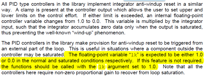
As stated below on page 42 of DCL user's guide, lk must be set to 1.0. I would like to know if this "1.0" is a logic high (3.3V) or a 0X0001 ?. Because in the F28069 example on CCS, I found this line in the interrupt routine:

lk = (float) AdcResult.ADCRESULT1;  // external clamp for anti-windup reset

DCL_runClamp_C1(&lk, 1.0f, 0.0f);  

Which I undertstant that lk is an analog input (0 - 4096). 

Please note also that I had to use DCL_RUNCLAMP_C2 instead of C1 since I am having build error on C1. 


  • Christian,

    I see your point.

    The "lk" argument to the controller is a floating-point number which should always be either 1.0f or 0.0f.  In that sense it could be thought of as a logical input, but it is a floating-point number which should only ever be one of those two values.  It's purpose is to enable the integrator to be reset if a part of the loop outside the controller saturates.

    What happens in the example code is that ADC result is formatted as a float and stored as "lk".  The clamp function should test this value tested to determine if it lies in the range +1 to -1 (arbitrary values for this example), then call the controller with either 0.0f or 1.0f depending on the result. So, I think the example code is wrong because it does not use the result of the clamp.  I will note that for revision in the next version.

    I think the code should be something like this:

    float32_t x;

    x = (float32_t) AdcResult.ADCRESULT1;

    lk = (float32_t) DCL_runClamp_C1(&x, 1.0f, 0.0f);

    uk = DCL_runPID_C4(&pid1, rk, yk, lk);

    The only major difference between the clamp functions is that C1 is implemented in assembly, while C2 is an inline C function.  Did you add the assembly file "DCL_clamp_C1.asm" to your project?

    BTW, from the page number you quote I think you might be on v3.1 of the DCL.  At some point you may like to download the latest version of C2000Ware which contains v3.2 of the library.  The PID controllers are the same, but you will find a few minor enhancements.

    Thanks for pointing this out.

    Regards,

    Richard

  • Hi Richards, 

    Thank you very much. It help a lot. I will download the latest version now. 

    But just to be clear, the float32_t x can be any external analog input , right ? 

    BR, 

    Christian

  • Hi Christian,

    Yes, correct.  Any external input, or it might come from another part of your program.  

    Regards,

    Richard

  • Hi Richard, 

    Please follow my code below. I am having the following warning: 

    *******************************************************************************************************************

    #10247-D null: creating output section "dclfuncs" without a SECTIONS

    *****************************************************************************

    And I have no value on uk via watch window. Clamp C1 function does not work so I set Ik value to 1.0f, but still no result on uk. Note that vk is 4095 and yk is between [0 - 1]. 

    //
    #include "F28x_Project.h"
    #include "DCLF32.h"
    #include "DCL.h"
    #include "DCL_fdlog.h"
    #include "DCL_TCM.h"


    long IdleLoopCount = 0;
    long IsrCount = 0;
    float rk = 0.25f;
    float yk;
    float lk = 1.0f;
    float uk;
    DCL_PID pid1 = PID_DEFAULTS;
    float vk;
    Uint16 tk;
    Uint16 ek;
    float pk = 0.001f;

    ////// teste fim

    // Function Prototypes
    //
    void ConfigureADC(void);
    void ConfigureEPWM(void);
    void SetupADCEpwm(Uint16 channel);
    interrupt void adca1_isr(void);


    void main(void)
    {
    //
    // Step 1. Initialize System Control:
    // PLL, WatchDog, enable Peripheral Clocks
    // This example function is found in the F2837xD_SysCtrl.c file.
    //
    InitSysCtrl();


    /////input xbar
    EALLOW;
    InputXbarRegs.INPUT5SELECT = 1;
    EDIS;
    ///////input xbar

    // Step 2. Initialize GPIO:
    // This example function is found in the F2837xD_Gpio.c file and
    // illustrates how to set the GPIO to it's default state.
    //
    InitGpio(); // Skipped for this example


    /////////OUTPUT X-BAR TEST ///////
    EALLOW;
    OutputXbarRegs.OUTPUT1MUX0TO15CFG.bit.MUX1 = 1;
    OutputXbarRegs.OUTPUT1MUXENABLE.bit.MUX1 = 1;
    OutputXbarRegs.OUTPUTLATCHENABLE.bit.OUTPUT1 = 0;
    OutputXbarRegs.OUTPUTINV.bit.OUTPUT1 = 0;
    EDIS;
    ////////OUTPUT X-BAR FIM //////

    //
    // Step 3. Clear all interrupts and initialize PIE vector table:
    // Disable CPU interrupts
    //
    DINT;

    //
    // Initialize the PIE control registers to their default state.
    // The default state is all PIE interrupts disabled and flags
    // are cleared.
    // This function is found in the F2837xD_PieCtrl.c file.
    //
    InitPieCtrl();

    // Disable CPU interrupts and clear all CPU interrupt flags:
    //
    IER = 0x0000;
    IFR = 0x0000;

    //
    // Initialize the PIE vector table with pointers to the shell Interrupt
    // Service Routines (ISR).
    // This will populate the entire table, even if the interrupt
    // is not used in this example. This is useful for debug purposes.
    // The shell ISR routines are found in F2837xD_DefaultIsr.c.
    // This function is found in F2837xD_PieVect.c.
    //
    InitPieVectTable();

    EINT; // Enable Global interrupt INTM
    ERTM; // Enable Global realtime interrupt DBGM
    //
    // Map ISR functions
    //
    EALLOW;
    PieVectTable.ADCA1_INT = &adca1_isr; //function for ADCA interrupt 1
    EDIS;

    //
    // Configure the ADC and power it up
    //
    ConfigureADC();

    //
    // Configure the ePWM
    //
    ConfigureEPWM();

    //
    // Setup the ADC for ePWM triggered conversions on channel 0
    //
    SetupADCEpwm(0);


    // Configure DAC
    //
    configureDAC(DAC_NUM);
    //
    // Enable global Interrupts and higher priority real-time debug events:
    //
    IER |= M_INT1; //Enable group 1 interrupts
    EINT; // Enable Global interrupt INTM
    ERTM; // Enable Global realtime interrupt DBGM

    //
    // Initialize results buffer
    //
    for(resultsIndex = 0; resultsIndex < RESULTS_BUFFER_SIZE; resultsIndex++)
    {
    AdcaResults[resultsIndex] = 0;
    }
    resultsIndex = 0;
    bufferFull = 0;

    //
    // enable PIE interrupt
    //
    PieCtrlRegs.PIEIER1.bit.INTx1 = 1;

    //
    // sync ePWM
    //
    EALLOW;
    CpuSysRegs.PCLKCR0.bit.TBCLKSYNC = 1;

    //
    //take conversions indefinitely in loop
    //
    do
    {
    //
    //start ePWM
    //
    EPwm1Regs.ETSEL.bit.SOCAEN = 1; //enable SOCA
    EPwm1Regs.TBCTL.bit.CTRMODE = 0; //unfreeze, and enter up count mode

    //
    //wait while ePWM causes ADC conversions, which then cause interrupts,
    //which fill the results buffer, eventually setting the bufferFull
    //flag
    //
    while(!bufferFull);
    bufferFull = 0; //clear the buffer full flag

    //
    //stop ePWM
    //
    EPwm1Regs.ETSEL.bit.SOCAEN = 0; //disable SOCA
    EPwm1Regs.TBCTL.bit.CTRMODE = 3; //freeze counter

    //
    //at this point, AdcaResults[] contains a sequence of conversions
    //from the selected channel
    //

    //
    //software breakpoint, hit run again to get updated conversions
    //
    asm(" ESTOP0");
    }


    while (1);

    }

    //
    // ConfigureADC - Write ADC configurations and power up the ADC for both
    // ADC A and ADC B
    //
    void ConfigureADC(void)
    {
    EALLOW;

    //
    //write configurations
    //
    AdcaRegs.ADCCTL2.bit.PRESCALE = 6; //set ADCCLK divider to /4
    AdcSetMode(ADC_ADCA, ADC_RESOLUTION_12BIT, ADC_SIGNALMODE_SINGLE);

    //
    //Set pulse positions to late
    //
    AdcaRegs.ADCCTL1.bit.INTPULSEPOS = 1;

    //
    //power up the ADC
    //
    AdcaRegs.ADCCTL1.bit.ADCPWDNZ = 1;

    //
    //delay for 1ms to allow ADC time to power up
    //
    DELAY_US(1000);

    EDIS;
    }

    //
    // ConfigureEPWM - Configure EPWM SOC and compare values
    //
    void ConfigureEPWM(void)
    {
    EALLOW;
    // Assumes ePWM clock is already enabled
    EPwm1Regs.ETSEL.bit.SOCAEN = 0; // Disable SOC on A group
    EPwm1Regs.ETSEL.bit.SOCASEL = 4; // Select SOC on up-count
    EPwm1Regs.ETPS.bit.SOCAPRD = 1; // Generate pulse on 1st event
    EPwm1Regs.CMPA.bit.CMPA = 0x0800; // Set compare A value to 2048 counts
    EPwm1Regs.TBPRD = 0x1000; // Set period to 4096 counts
    EPwm1Regs.TBCTL.bit.CTRMODE = 3; // freeze counter
    EDIS;
    }

    //
    // SetupADCEpwm - Setup ADC EPWM acquisition window
    //
    void SetupADCEpwm(Uint16 channel)
    {
    Uint16 acqps;

    //
    //determine minimum acquisition window (in SYSCLKS) based on resolution
    //
    if(ADC_RESOLUTION_12BIT == AdcaRegs.ADCCTL2.bit.RESOLUTION)
    {
    acqps = 14; //75ns
    }
    else //resolution is 16-bit
    {
    acqps = 63; //320ns
    }

    //
    //Select the channels to convert and end of conversion flag
    //
    EALLOW;
    AdcaRegs.ADCSOC0CTL.bit.CHSEL = 2; //SOC0 will convert pin A2
    AdcaRegs.ADCSOC0CTL.bit.ACQPS = acqps; //sample window is 100 SYSCLK cycles
    AdcaRegs.ADCSOC0CTL.bit.TRIGSEL = 5; //trigger on ePWM1 SOCA/C
    AdcaRegs.ADCSOC1CTL.bit.CHSEL = 1; //SOC0 will convert pin A3
    AdcaRegs.ADCSOC1CTL.bit.ACQPS = acqps; //sample window is 100 SYSCLK cycles
    AdcaRegs.ADCSOC1CTL.bit.TRIGSEL = 5; //trigger on ePWM1 SOCA/C
    AdcaRegs.ADCINTSEL1N2.bit.INT1SEL = 0; //end of SOC0 will set INT1 flag
    AdcaRegs.ADCINTSEL1N2.bit.INT1E = 1; //enable INT1 flag
    AdcaRegs.ADCINTFLGCLR.bit.ADCINT1 = 1; //make sure INT1 flag is cleared
    AdcaRegs.ADCINTSEL1N2.bit.INT1SEL = 1; //end of SOC0 will set INT1 flag
    AdcaRegs.ADCINTSEL1N2.bit.INT1E = 1; //enable INT1 flag
    AdcaRegs.ADCINTFLGCLR.bit.ADCINT1 = 1; //make sure INT1 flag is cleared
    EDIS;
    }

    //
    // adca1_isr - Read ADC Buffer in ISR
    //
    interrupt void adca1_isr(void)
    {


    yk = ( (float) AdcaResultRegs.ADCRESULT0 - 2048.0f) / 2047.0f;
    vk = AdcaResultRegs.ADCRESULT1;
     lk = DCL_runClamp_C1(&vk, 1.0f, 0.0f); // external clamp for anti-windup reset


    // run PID controller

    uk = DCL_runPID_C4(&pid1, rk, yk, lk);

    ADCINTFLGCLR.bit.ADCINT1 = 1; //clear INT1 flag

    PieCtrlRegs.PIEACK.all = PIEACK_GROUP1;
    ////////ARQUIVO ORIGINAL
    }

  • Hi Richard, 

    I did a second test with fixed value:

    rf = 0.25f

    yk = 2.5f

    lk = 1.0f;

    but still no result  on uk.

    br,

    christian

  • Hi Christian,

    When you add any of the DCL assembly modules to your project you'll have to declare the "dclfuncs" section in your linker command file.  In most cases you can put it in the same memory block as your .ebss section without any issues.  There are examples of this in the DCL linker files at:

    C:\ti\c2000\C2000Ware_2_00_00_02\libraries\control\DCL\c28\cmd

    The clamp function returns a 16-bit integer, either 0x0 or 0x1, depending on whether the variable (vk in this case) has saturated or not.  You can't pass the result to the controller because that expects a float.  If you look back at my previous post, the return value from the clamp function was typecast as float:

    lk = (float32_t) DCL_runClamp_C1(&x, 1.0f, 0.0f);

    You also need to typecast vk in your code, because the RESULT register contains an integer and the clamp expects to see a float.  Please look again at the example above.

    Regards,

    Richard