Tool/software: Code Composer Studio
Hello Everyone,
I have a problem with my C200 Piccolo microkontroller.
I would like to measure the time with an Interrupt Service Routine .
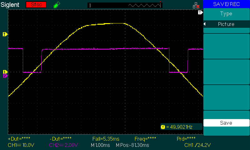
The signal wich I measur is in der picture below. the high time is 8.75 ms und the bottom time is 1.25 ms,
wich I measured with an oscilloskope.
My problem is that I cant measur the right time with the microkontroller, once I test the programm with one timer and one interrrpt it works, but now it doesnt work anymore and the old programm too.
The time I measur with the microkontrolle is in the picture below too (purple line).
The wrong time I measure is also in the picture below (yellow market).
Do you have any ideas where is the problem?
Thanks
// Included Files
#include "DSP28x_Project.h" // Device Headerfile and Examples Include File
// Function Prototypes
__interrupt void xint1_isr(void);
__interrupt void xint2_isr(void);
void InitInterrupt1_2(void);
void InitTimer2(void);
void InitTimer3(void);
////////////// Globals //////////////
//--> grid
double Time_rising_edge_Grid = 0.0;
double Time_falling_edge_Grid = 0.0;
uint32_t Cyclen_rising_edge_Grid = 0.0;
uint32_t Cyceln_falling_edge_Grid = 0.0;
//--> Modulation
double Time_rising_edge_Mod = 0.0;
double Time_falling_edge_Mod = 0.0;
uint32_t Cyclen_rising_edge_Mod = 0.0;
uint32_t Cyceln_falling_edge_Mod = 0.0;
//--> Variables
double PeriodTime_Grid = 0.0;
double PeriodTime_Mod = 0.0;
uint8_t x = 0;
uint16_t varHelp = 0;
uint16_t varHelp2 = 0;
uint16_t State = 0;
uint16_t State2 = 0;
void main(void) // main
{
//
// WARNING: Always ensure you call memcpy before running any functions from
// RAM InitSysCtrl includes a call to a RAM based function and without a
// call to memcpy first, the processor will go "into the weeds"
//
#ifdef _FLASH
memcpy(&RamfuncsRunStart, &RamfuncsLoadStart, (size_t)&RamfuncsLoadSize);
#endif
//
// Step 1. Initialize System Control:
// PLL, WatchDog, enable Peripheral Clocks
// This example function is found in the f2802x_SysCtrl.c file.
//
InitSysCtrl();
//
// Step 2. Initialize GPIO:
// This example function is found in the f2802x_Gpio.c file and
// illustrates how to set the GPIO to it's default state.
//
//InitGpio(); // Skipped for this example
//
// Step 3. Clear all interrupts and initialize PIE vector table:
// Disable CPU interrupts
//
DINT;
//
// Initialize PIE control registers to their default state.
// The default state is all PIE interrupts disabled and flags
// are cleared.
// This function is found in the f2802x_PieCtrl.c file.
//
InitPieCtrl();
//
// Disable CPU interrupts and clear all CPU interrupt flags
//
IER = 0x0000;
IFR = 0x0000;
//
// Initialize the PIE vector table with pointers to the shell Interrupt
// Service Routines (ISR).
// This will populate the entire table, even if the interrupt
// is not used in this example. This is useful for debug purposes.
// The shell ISR routines are found in f2802x_DefaultIsr.c.
// This function is found in f2802x_PieVect.c.
//
InitPieVectTable();
InitInterrupt1_2();
InitTimer2(); // Time measure for Int1 modulation
InitTimer3(); // Time measure for Int1 grid
for(;;)
{
//---> Time calculation grid
Time_falling_edge_Grid = (double)Cyceln_falling_edge_Grid/60000000*4*128; //HSPCLKDIV = TB_DIV4 und CLKDIV = 0b111;(128)
Time_rising_edge_Grid = (double)Cyclen_rising_edge_Grid/60000000*4*128; //HSPCLKDIV = TB_DIV4 und CLKDIV = 0b111;(128)
PeriodTime_Grid = Time_falling_edge_Grid + Time_rising_edge_Grid;
//---> Time calculation modulation
Time_falling_edge_Mod = (double)Cyceln_falling_edge_Mod/60000000*4*128; //HSPCLKDIV = TB_DIV4 und CLKDIV = 0b111;(128)
Time_rising_edge_Mod = (double)Cyclen_rising_edge_Mod/60000000*4*128; //HSPCLKDIV = TB_DIV4 und CLKDIV = 0b111;(128)
PeriodTime_Mod = Time_falling_edge_Mod + Time_rising_edge_Mod;
}
}
__interrupt void //ISR_1 Grid time measure
xint1_isr(void) // rising and falling detector
{
if(State == 0)
{
if(GpioDataRegs.GPADAT.bit.GPIO0 == 0) // falling edge
{
EPwm2Regs.TBCTR = 0x0000; // Set Counter to zero
varHelp = 1;
}
if(GpioDataRegs.GPADAT.bit.GPIO0 == 1 && varHelp == 1) // rising edge
{
Cyceln_falling_edge_Grid = EPwm2Regs.TBCTR; // save time cycles
EPwm2Regs.TBCTR = 0x0000; // Set Counter to zero
State = 1;
}
}
if(State == 1)
{
if(GpioDataRegs.GPADAT.bit.GPIO0 == 0)
{
Cyclen_rising_edge_Grid = EPwm2Regs.TBCTR; // save time cycles
State = 0;
}
}
// Acknowledge this interrupt to get more from group 1
PieCtrlRegs.PIEACK.all = PIEACK_GROUP1;
}
__interrupt void //ISR_2 Modulation time measure
xint2_isr(void) // rising and falling detector
{
if(State2 == 0)
{
if(GpioDataRegs.GPADAT.bit.GPIO1 == 0) // first read falling edge ---> then rising to measure the bottom time
{
EPwm3Regs.TBCTR = 0x0000; // Set Counter to zero
varHelp2 = 1;
}
if(GpioDataRegs.GPADAT.bit.GPIO1 == 1 && varHelp2 == 1) // rising edge
{
Cyceln_falling_edge_Mod = EPwm3Regs.TBCTR; // save time cycles
EPwm3Regs.TBCTR = 0x0000; // Set Counter to zero to measure the top time
State2 = 1;
}
}
if(State2 == 1)
{
if(GpioDataRegs.GPADAT.bit.GPIO1 == 0)
{
Cyclen_rising_edge_Mod = EPwm3Regs.TBCTR; // save time cycles
State2 = 0;
}
}
// Acknowledge this interrupt to get more from group 1
PieCtrlRegs.PIEACK.all = PIEACK_GROUP1;
}
void
InitTimer2() // Time measure grid sine
{
EPwm2Regs.TBPRD = 0xFFFF; // Set timer period
EPwm2Regs.TBPHS.half.TBPHS = 0x0000; // Phase is 0
EPwm2Regs.TBCTR = 0x0000; // Clear counter
//
// Setup TBCLK
//
EPwm2Regs.TBCTL.bit.CTRMODE = TB_COUNT_UP; // Count up eigentlich = TB_COUNT_UPDOWN
EPwm2Regs.TBCTL.bit.PHSEN = TB_DISABLE; // Disable phase loading
EPwm2Regs.TBCTL.bit.HSPCLKDIV = TB_DIV4; // Clock ratio to SYSCLKOUT // prescaler = 4
EPwm2Regs.TBCTL.bit.CLKDIV = 0b111; //TB_DIV4; // 0b111 = prescaler =128
//------> gesammter Prescaler = 128*4 = 512
}
void
InitTimer3() // Time measure modulation sine
{
EPwm3Regs.TBPRD = 0xFFFF; // Set timer period
EPwm3Regs.TBPHS.half.TBPHS = 0x0000; // Phase is 0
EPwm3Regs.TBCTR = 0x0000; // Clear counter
//
// Setup TBCLK
//
EPwm3Regs.TBCTL.bit.CTRMODE = TB_COUNT_UP; // Count up
EPwm3Regs.TBCTL.bit.PHSEN = TB_DISABLE; // Disable phase loading
EPwm3Regs.TBCTL.bit.HSPCLKDIV = TB_DIV4; // Clock ratio to SYSCLKOUT // prescaler = 4
EPwm3Regs.TBCTL.bit.CLKDIV = 0b111; //TB_DIV4; // 0b111 = prescaler =128
//------> gesammter Prescaler = 128*4 = 512
}
void
InitInterrupt1_2()
{
// Interrupts that are used in this example are re-mapped to
// ISR functions found within this file.
EALLOW; // This is needed to write to EALLOW protected registers
PieVectTable.XINT1 = &xint1_isr;
PieVectTable.XINT2 = &xint2_isr;
EDIS; // This is needed to disable write to EALLOW protected registers
// Enable XINT1 and XINT2 in the PIE: Group 1 interrupt 4 & 5
// Enable INT1 which is connected to WAKEINT:
PieCtrlRegs.PIECTRL.bit.ENPIE = 1; // Enable the PIE block
PieCtrlRegs.PIEIER1.bit.INTx4 = 1; // Enable PIE Group 1 INT4
PieCtrlRegs.PIEIER1.bit.INTx5 = 1; // Enable PIE Group 1 INT5
IER |= M_INT1; // Enable CPU INT1
EINT; // Enable Global Interrupts
// GPIO0 and GPIO1 are inputs
EALLOW;
GpioCtrlRegs.GPAMUX1.bit.GPIO0 = 0; // GPIO
GpioCtrlRegs.GPADIR.bit.GPIO0 = 0; // input
GpioCtrlRegs.GPAQSEL1.bit.GPIO0 = 0; // XINT1 Synch to SYSCLKOUT only
GpioCtrlRegs.GPAMUX1.bit.GPIO1 = 0; // GPIO
GpioCtrlRegs.GPADIR.bit.GPIO1 = 0; // input
GpioCtrlRegs.GPAQSEL1.bit.GPIO1 = 0; // eigentlich2 ????// XINT2 Qual using 6 samples
// Each sampling window is 510*SYSCLKOUT
GpioCtrlRegs.GPACTRL.bit.QUALPRD0 = 1;//eigentlich = 0xFF;
EDIS;
// GPIO0 is XINT1, GPIO1 is XINT2
EALLOW;
GpioIntRegs.GPIOXINT1SEL.bit.GPIOSEL = 0; // XINT1 is GPIO0
GpioIntRegs.GPIOXINT2SEL.bit.GPIOSEL = 1; // XINT2 is GPIO1
EDIS;
// Configure XINT1 ????? und XINT2???
XIntruptRegs.XINT1CR.bit.POLARITY = 3; // Falling and rising edge // 0: falling, 1: rising, 2: falling, 3: both
XIntruptRegs.XINT2CR.bit.POLARITY = 3; // Rising edge interrupt // 0: falling, 1: rising, 2: falling, 3: both
// Enable XINT1 and XINT2
XIntruptRegs.XINT1CR.bit.ENABLE = 1; // Enable XINT1
XIntruptRegs.XINT2CR.bit.ENABLE = 1; // Enable XINT2
}