This thread has been locked.

If you have a related question, please click the "Ask a related question" button in the top right corner. The newly created question will be automatically linked to this question.

LAUNCHXL-F280049C: Error while uploading ending in process terminated.

Part Number: LAUNCHXL-F280049C
Other Parts Discussed in Thread: C2000WARE,

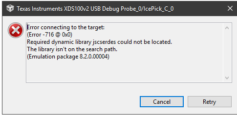
I have the latest version of CCS and a brand new F280049C.

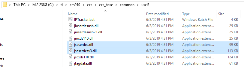
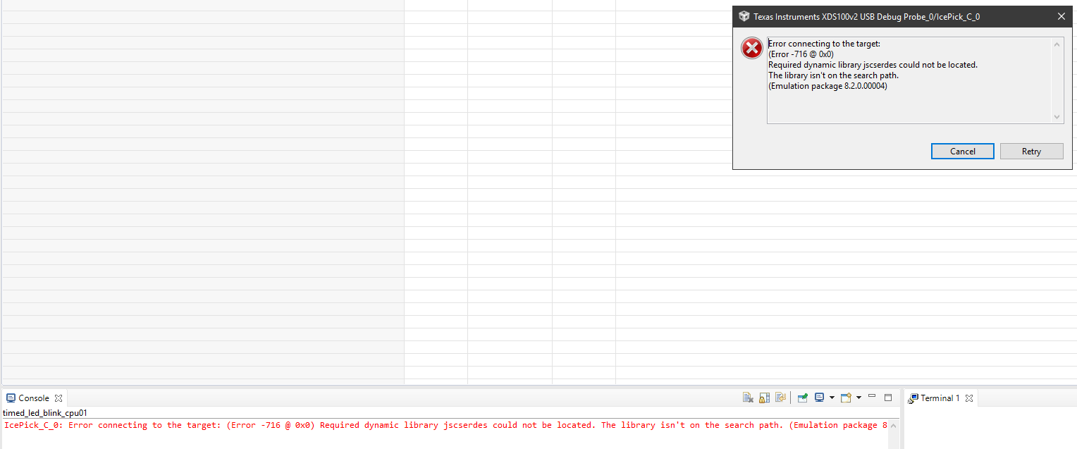
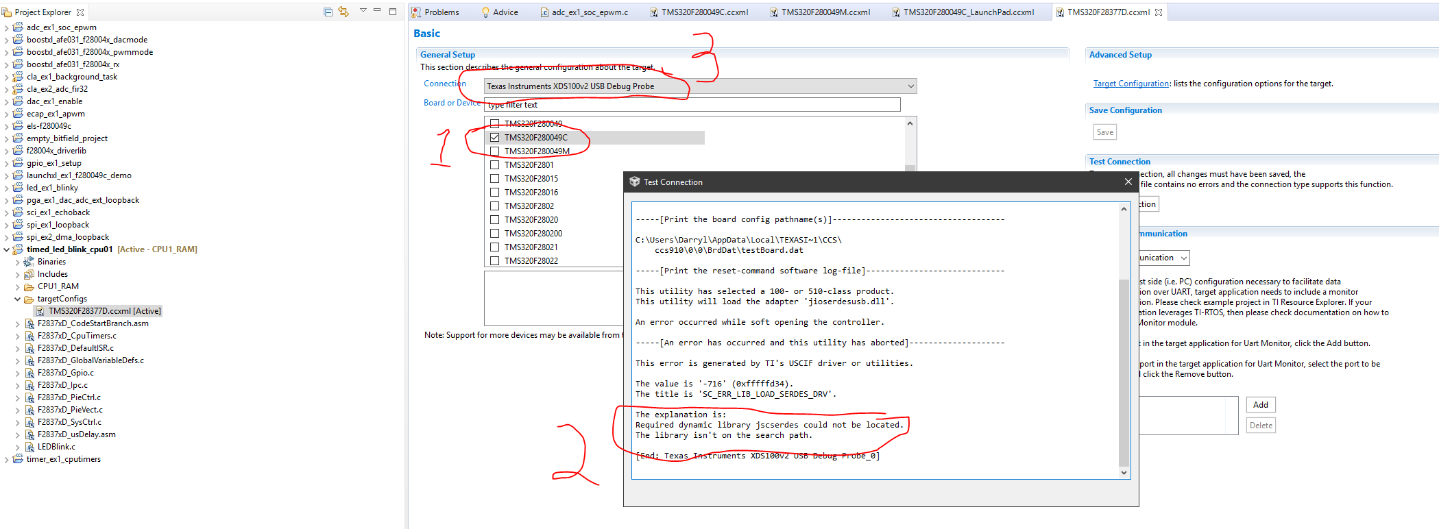
Above error occurs when uploading to board. I can only get 1 or 2 example programs to fully load properly. I cannot find this file anywhere.

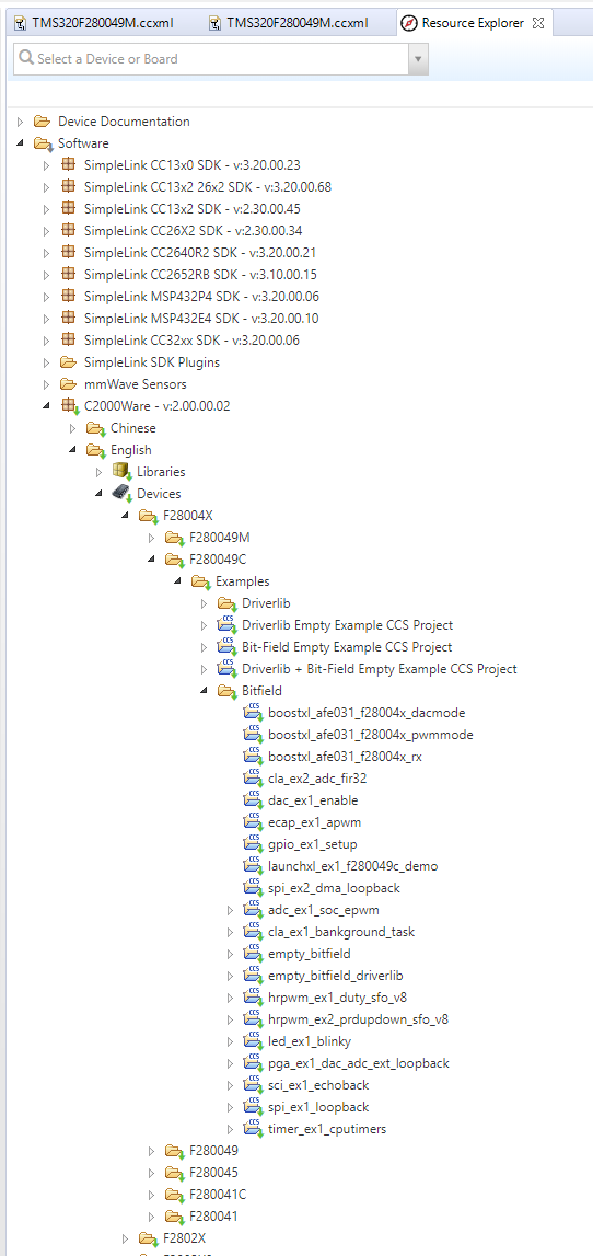
Will this file, if installed, allow all the demos to upload and run? Can I get the file from this forum? If so, i'll be greatful.

  • Hi Darryl,

    This dynamic library should be in your CCS directory, for example C:\ti\ccsX\ccs\ccs_base\common\uscif

    Did you install CCS in your C-drive? If you are missing this dynamic library you might be missing others as well. Please uninstall and re-install CCS to see if that solves the issue.

    Also, please check out the following post: https://e2e.ti.com/support/microcontrollers/c2000/f/171/t/490091

    The post describes a similar problem that was solved by uninstalling and then reinstalling CCS without an antivirus software.

    Best Regards,

    Marlyn

  • Marlyn;

    I uninstalled ccs9 then reinstalled it. Same same.

    However, the project I intend to work on loads just fine.

    But I want to work thru the examples first.

    As you can see in the captures, I do have the file right where you said it would be.

    Any more ideas?

    Darryl

  • Hi Darryl,

    Where is the project that you intend to work on located?

    Are the examples you are trying to load coming from C2000Ware? If so, do the ones that load correctly, load every time or are you now not able to load any example project?

    A few suggestions in the mean time,

    1) Keep your device plugged in

    2) Uninstall the drivers (both Class Data Port and Class Debug Probe)

    3) Disconnect the device from the computer

    4) Install the drivers from http://processors.wiki.ti.com/index.php/XDS_Emulation_Software_Package 

    5) Connect the device to the computer

    6) In Device Manager, under 'Action' click on 'Scan for Hardware Changes', you should see the drivers appear again.

    Best,

    Marlyn

  • Darryl,

    The error seems to indicate what Marlyn mentioned: a faulty install. However, since you showed the files present on the CCS install directory, I have another suspicion. 

    If you are using the built-in debug probe of the The LAUNCHXL-F280049C, its model is the XDS110 Debug Probe, not the XDS100v2. 

    This is a common occurrence if you created/imported a project from the C2000Ware, since all the current projects seem misconfigured and point to the XDS100v2. 

    Please check the short clip below to learn how to proceed to change this:

    https://youtu.be/4ZoXwM3-Szw

    Hope this helps,

    Rafael


  • Rafael

    I successfully loaded the correct debug version. Capture 3 is the result.

    Marlyn

    The project is located in the same folder as the examples after i imported them. (C:\Users\Darryl\workspace_v9)

    Yes, loadable examples load every time.

    I switched out the cable but same result.

    I uninstalled the old drivers and installed XDS Emulation Software Package, then tried to load project and got the following. (capture 4)

  • Darryl,

    After installing the drivers again were you able to see the 'Texas Instruments Debug Probes' in Device Manager?

    Could you please try using another USB port on your computer.

    If that still does not work then we can try something else,

    Please navigate to the directory that is shown in (Capture 4) screenshot you provided. Open the 'XDS110SupportReadMe' file and follow the steps for 'Updating the Firmware Using xdsdfu'. Something might have gone wrong while re-installing the drivers. After you have done this try to connect and load a program again.

    Best,

    Marlyn

  • Darryl,

    As Marlyn mentioned, the error shown in your last capture is indicative of a probe that is unable to be found by CCS - this can be caused by a problem in the install or the drivers themselves. Additional details can be found at the Debugging JTAG page below (just search for the error number 260).

    http://software-dl.ti.com/ccs/esd/documents/ccs_debugging_jtag_connectivity_issues.html 

    For details on the device drivers, etc. please check the section troubleshooting of the XDS110 page at: 

    http://software-dl.ti.com/ccs/esd/documents/xdsdebugprobes/emu_xds110.html 

    The page above contains additional details on how to update the firmware and troubleshoot other scenarios. 

    By the way, the Capture3.PNG file still shows the XDS100v2 in the title of the dialog box. 

    Regards,

    Rafael

  • Marlyn,

    Yes the Debug Probes are listed in device manager. capture attached.

    I did try other ports. Both usb2 and usb3. No luck

    Successfully updated xdsdfu firmware. No luck

    Rafael,

    I'll check out the pdf's later. Don't have time right now. My project loads fine so I'm not too concerned about the examples. One thing i did notice is that the examples that I checked were set up for a different board. see capture 6 below. next to #1 I had to change to my board. A different board was originally selected. I don't know if this is normal or not. After I made the correction and saved. I tried again to load an example with no success.

    I'm going to set "this resolved my issue" but before i do, i have one last question. Pertaining to the switches on the board, which direction is  1 and which is 0, or on/off? I see a dot on one side and a "b" "y" on the other side. Please explain.

    And referring to your final point about xds110v2 listed. It's correct now. see below.

  • Darryl,

    Darryl Ols said:
    I'll check out the pdf's later. Don't have time right now. My project loads fine so I'm not too concerned about the examples. One thing i did notice is that the examples that I checked were set up for a different board. see capture 6 below. next to #1 I had to change to my board. A different board was originally selected. I don't know if this is normal or not. After I made the correction and saved. I tried again to load an example with no success.

    The example that you are trying to load is for another device, the F2837xD. This is why the target configuration file had the other device selected. Simply changing the configuration file for your device will not make the program loadable. While there might be similarities between the two devices, the header files along with other files are specific to the device the project is intended for. If you are using the F28004x device then please only try to load projects for that device.

    Darryl Ols said:
    I'm going to set "this resolved my issue" but before i do, i have one last question. Pertaining to the switches on the board, which direction is  1 and which is 0, or on/off? I see a dot on one side and a "b" "y" on the other side. Please explain.

    Can you please provide a switch number?

    Darryl Ols said:
    And referring to your final point about xds110v2 listed. It's correct now. see below

    Right under "2" in your screenshot it says "XDS100v2". The F28004x Launchpad has the XDS110. Please follow the video Rafael had attached to change the target configuration properly. You will need to open the 'Target Configuration File' for the F28004x device you are trying to load and then switch the connection type to 'Texas Instruments XDS110 USB Debug Probe', click 'Save' then proceed to 'Target Configuration' under advanced setup. Within this window click on the 'Texas Instruments XDS110 USB Debug Probe 0' and make sure to select 'cJTAG (1149.7) 2-pin advanced modes' under the 'JTAG / SWD / cJTAG Mode' option. After this click on 'Save' then 'Test Connection'. Make sure to do this for all of the F28004x projects you try to load.  

    Below are some screenshots to show what this looks like.

    Best Regards,

    Marlyn

  • Thanks for the info about the wrong board for the project. I was wondering if this was the case. However I found all these examples in the folder for this board. see capture 8. So that's why I thought there was no problem on my end. Please correct me if I'm wrong.

    Anyway, switches S3,S4,S6,S8,S9 are the ones used by my project. S2 is labeled properly.  but the others, not so much.

  • Darryl,

    Darryl Ols said:
    However I found all these examples in the folder for this board. see capture 8. So that's why I thought there was no problem on my end. Please correct me if I'm wrong.

    The examples that you have shown in the screen capture should all be okay for the LAUNCHXL-F280049C.

    Darryl Ols said:
    switches S3,S4,S6,S8,S9 are the ones used by my project. S2 is labeled properly.  but the others, not so much.

    Thank you for bringing this to our attention. I have filed an internal note to update the documentation with clear indication of the switch states. For now, please reference the schematics for the device, or the silkscreen of the device itself. For example in the user guide:

    S3 is the QEP select so in the 'eQEP' section it states the following:

    "The LaunchPad has the ability to connect to two independent linear or rotary encoders through the F28004x on-chip eQEP interfaces: Header J12 is connected to eQEP1 and header J13 is connected to eQEP2. By default, this connection is not active and the GPIOs are routed to the BoosterPack connectors."

    So if you want to use eQEP1 then switch 'B' to J12 instead of BP (Booster Pack), and if you want to use eQEP2 then flip 'C' down to J13.

    I hope this answers your questions.

    Best Regards,

    Marlyn