


Hi,
I have configured TMS320F28335 as a master and wifi module as slave over SPI. So master sending command and Wi-Fi module responding as expected,as I have observed on Wi-Fi debug tool.
SPI transmission working fine,when I am sending System RESET command Wi-FI module responds with wifi_evt_sytem_boot as shown in the below screenshot
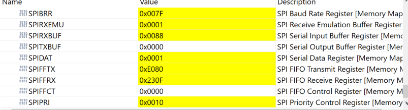
At MISO pin I have obseved that I am getting data as send by the Wi-Fi module.But at RXBUF I am getting only three words,Please find below value of SPIFFRX register which shows value of numer of character receivedv i.e. 3
SPIFFRX =0x230F;
also find below code that I am using for SPI reception,
void main(void)
{
Uint16 sdata; // send data
Uint16 rdata1; // received data
//
// Step 1. Initialize System Control:
// PLL, WatchDog, enable Peripheral Clocks
// This example function is found in the DSP2833x_SysCtrl.c file.
//
InitSysCtrl();
//
// Step 2. Initialize GPIO:
// This example function is found in the DSP2833x_Gpio.c file and
// illustrates how to set the GPIO to it's default state.
//
// InitGpio(); // Skipped for this example
//
// Setup only the GP I/O only for SPI-A functionality
// This function is found in DSP2833x_Spi.c
//
InitSpiaGpio();
//
// Step 3. Clear all interrupts and initialize PIE vector table:
// Disable CPU interrupts
//
DINT;
//
// Initialize PIE control registers to their default state.
// The default state is all PIE interrupts disabled and flags
// are cleared.
// This function is found in the DSP2833x_PieCtrl.c file.
//
InitPieCtrl();
//
// Disable CPU interrupts and clear all CPU interrupt flags:
//
IER = 0x0000;
IFR = 0x0000;
//
// Initialize the PIE vector table with pointers to the shell Interrupt
// Service Routines (ISR).
// This will populate the entire table, even if the interrupt
// is not used in this example. This is useful for debug purposes.
// The shell ISR routines are found in DSP2833x_DefaultIsr.c.
// This function is found in DSP2833x_PieVect.c.
//
InitPieVectTable();
//
// Step 4. Initialize all the Device Peripherals:
// This function is found in DSP2833x_InitPeripherals.c
//
// InitPeripherals(); // Not required for this example
spi_fifo_init(); // Initialize the Spi FIFO
spi_init(); // init SPI
//
// Step 5. User specific code:
//
// send_BG_cmd(wifi_cmd_sme_wifi_ON,0);
send_BG_cmd(wifi_cmd_sme_system_reset,1);
//
// Interrupts are not used in this example.
//
sdata = 0x0000;
for(;;)
{
//
// Transmit data
//
//spi_xmit(sdata);
//
// Wait until data is received
//
while(SpiaRegs.SPIFFRX.bit.RXFFST!<10)
{
}
rdata[0] = SpiaRegs.SPIRXBUF;
rdata[1] = SpiaRegs.SPIRXBUF;
rdata[2] = SpiaRegs.SPIRXBUF;
rdata[3] = SpiaRegs.SPIRXBUF;
rdata[4] = SpiaRegs.SPIRXBUF;
rdata[5] = SpiaRegs.SPIRXBUF;
rdata[6] = SpiaRegs.SPIRXBUF;
rdata[7] = SpiaRegs.SPIRXBUF;
rdata[8] = SpiaRegs.SPIRXBUF;
rdata[9] = SpiaRegs.SPIRXBUF;
rdata[10] = SpiaRegs.SPIRXBUF;
rdata[11] = SpiaRegs.SPIRXBUF;
rdata[12] = SpiaRegs.SPIRXBUF;
rdata[13] = SpiaRegs.SPIRXBUF;
rdata[14] = SpiaRegs.SPIRXBUF;
if(rdata[0] == 0x0802)send_BG_cmd(wifi_cmd_sme_wifi_OFF,0);
/*
// Check against sent data
//
rdata1 = SpiaRegs.SPIRXBUF;
if(rdata != sdata)
{
error();
}
sdata++;*/
}
}
Please suggest the solution to read more than 3 words.
Thanks & Regards,
Sachin
