This thread has been locked.

If you have a related question, please click the "Ask a related question" button in the top right corner. The newly created question will be automatically linked to this question.

TMS320F28379D: Matlab Simulink Embedded Coder ePWM 12B Output MUX

Part Number: TMS320F28379D
Other Parts Discussed in Thread: LAUNCHXL-F28379D

Hello guys

how can I connect the ePWM12B signal to an Pin in Simulink with the "Embedded Coder Support Package for Texas Instruments C2000 Processors"?

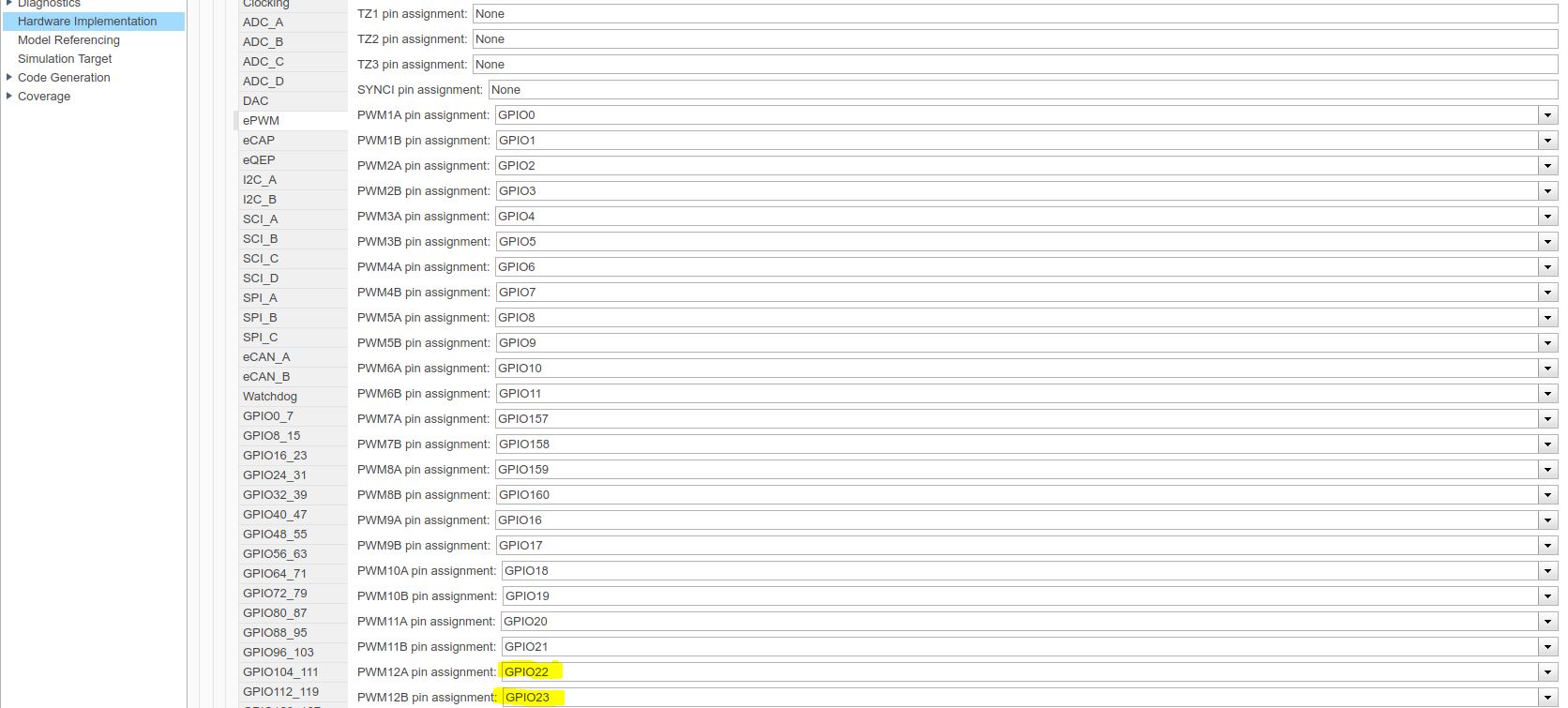
I want to connect the GPIO23 to an InputxBar and from this Input to an OutputxBar, which is connect to Pin 34 on the board.

I don't find the option to configure this.

  • Hi,

    The configuration option for this is not supported as of now.

    But since this is onetime configuration, you can use the custom code block under Simulink coder in SL library, use System Initialize block to provide the handwritten code which does this configuration. That will generate the code as part of init and should configure the X-BAR.

  • Hi,

    I tried the System Initialize block but it don't work. The Diagnostic Viewer only show the error:

    Error(s) encountered while building "PWM3PHASE_V4": ### Failed to generate all binary outputs.

    I wrote this code in the System Initialize block:

    #include "F2837xD_device.h"                                                                                                                                                  
    #include "F2837xD_Examples.h"                                                                                                                                                
    void InitEPwm12Gpio(void)                                                                                                                                                    
    {                                                                                                                                                                            
    //    EPWM12 (GPIO22 and GPIO23) is not completely accessible from board LAUNCHXl-F28379D. GPIO22 is accessible through Pin 8 of LAUNCHXL-F28379D (Table User Guide).        
    //    GPIO23 is not accessible through any pin                                                                                                                               
    //    Here the InputXbar and OutputXbar are used to route GPIO23 out.                                                                                                        
    //    This is described in: TMS320F2837xD Dual-Core Delfino Microcontrollers - Technical Reference Manual                                                                    
    //    From InputXbar the INPUT1 is selected because it can route the signals to OutputXbar (page 1153).                                                                      
    //    From Reference manual - Table 7-8. GPIO Muxed Pins                                                                                                                     
    //    GPIO22 is EPWM12A                                                                                                                                                      
    //    GPIO23 is EPWM12B                                                                                                                                                      
        EALLOW;                                                                                                                                                                  
        GpioCtrlRegs.GPAPUD.bit.GPIO22 = 1; // Disable pull-up                                                                                                                   
        GpioCtrlRegs.GPAPUD.bit.GPIO23 = 1; // Disable pull-up                                                                                                                   
        GpioCtrlRegs.GPAMUX2.bit.GPIO22 = 1;                                                                                                                                     
        GpioCtrlRegs.GPAMUX2.bit.GPIO23 = 1;                                                                                                                                     
        GpioCtrlRegs.GPAGMUX2.bit.GPIO22 = 1;                                                                                                                                    
        GpioCtrlRegs.GPAGMUX2.bit.GPIO23 = 1;                                                                                                                                    
        InputXbarRegs.INPUT1SELECT = 23; //Selecting GPIO23 to go to INPUT1 of InputXbar                                                                                         
    //    From User Guide, one sees that GPIO24 (Pin 34) is available for OUTPUTXBAR1. INPUT1 will be routed to this OUTPUT                                                      
        OutputXbarRegs.OUTPUT1MUX0TO15CFG.bit.MUX1 = 1; // Select INPUTXBAR1 from InputXbar to be the OUTPUT1. Reference Manual - Table 8-3. Output X-Bar Mux Configuration Table
        OutputXbarRegs.OUTPUT1MUXENABLE.bit.MUX1 = 1; // Enable Mux                                                                                                              
        GpioCtrlRegs.GPAMUX2.bit.GPIO24 = 1; // Configure GPIO24 as EPWM12B                                                                                                      
        GpioCtrlRegs.GPAPUD.bit.GPIO24 = 1; // Disable pull-up on GPIO24 (EPWM12B)                                                                                               
        EDIS;                                                                                                                                                                    
    }           

    Didn't know what I did wrong.

    Thank you in advance.


  • Hi,

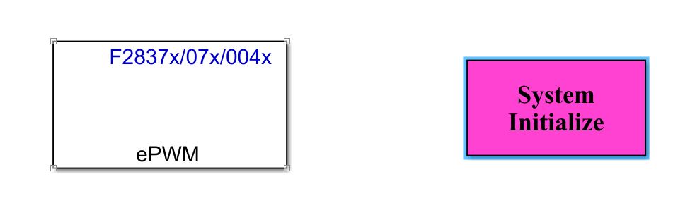
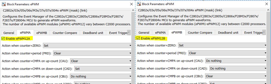
    I just included the ePWM block from C2000 block library and configured both EPWM12A and EPWM12B for the PWM output. I could verify the output on the EPWM12A using a DSO. Then using the System init block I added the following lines of code:

    EALLOW;                                       
    InputXbarRegs.INPUT1SELECT = 23;              
    OutputXbarRegs.OUTPUT1MUX0TO15CFG.bit.MUX1 = 1;
    OutputXbarRegs.OUTPUT1MUXENABLE.bit.MUX1 = 1; 
    EDIS;

    That based on our understanding should route the EPWM12B to GPIO24 which is on J4 - 34 header.

    But I don't see any output on this pin. So I am not sure if we can have this approach in place.

    I am under the impression that only external input on GPIO can be used and not the internal signal.

    Can we get this understanding confirmed from TI friends.

  • Now I tried to write the extra code to set the pin in this section:

    ->Configuration Parameters

    ->Simulation Target

    ->Source file

    But it also doesn't work...

    Somebody else who has an idea?

  • Hi,

    As Venkatesh explained, it is possible to route ePWM outputs to another GPIO using combination of Input X-BAR and Output X-BAR but still this has some constraints. Although Input X-Bar is accessible to all the GPIOs but Output X-Bar cannot route sinals to all GPIOs so need to be careful with that. But your desired configuration i.e. GPI023 (ePWM12B) -> GPIO34 is possible. 

    Configure Input X-Bar to connect GPIO23 and INPUT1 and then configure OUTPUT X-BAR to connect INPUT1 and OUTPUT1. Also it is important to note that The signal will only be seen on the GPIO if the proper OUTPUTx muxing options are selected via the GpioCtrlRegs.GPxMUX and GpioCtrlRegs.GPxGMUX registers.

    If my reply answers your question please click on "This resolved my issue" button located at the bottom of my post.

    Regards

    Himanshu

  • Hi,

    The following configuration worked for me with PWM output on pin 34.

    Regards,

    Venkatesh C

  • Hello,

    Thanks for your reply.

    But I still have a problem.

    I know what c-code I need to route the PWM12B-Signal to Pin, I posted it earlier in the thread.

    I don't get it integrated in my Matlab/Simulink Project.

    Till now i tried to write the extra custom code in an "System Initiailze-Block", "Model Source-Block" and in the "Configuration Parameters/Simulation Target/Source file - window".

    Thats the code I used:

    #include "F2837xD_device.h"
    #include "F2837xD_Examples.h"

    void InitEPwm12Gpio(void)
    {
    //    EPWM12 (GPIO22 and GPIO23) is not completely accessible from board LAUNCHXl-F28379D. GPIO22 is accessible through Pin 8 of LAUNCHXL-F28379D (Table User Guide).
    //    GPIO23 is not accessible through any pin
    //    Here the InputXbar and OutputXbar are used to route GPIO23 out.
    //    This is described in: TMS320F2837xD Dual-Core Delfino Microcontrollers - Technical Reference Manual

    //    From InputXbar the INPUT1 is selected because it can route the signals to OutputXbar (page 1153).

    //    From Reference manual - Table 7-8. GPIO Muxed Pins
    //    GPIO22 is EPWM12A
    //    GPIO23 is EPWM12B

        EALLOW;

        GpioCtrlRegs.GPAPUD.bit.GPIO23 = 1; // Disable pull-up

        GpioCtrlRegs.GPAMUX2.bit.GPIO23 = 1;

        GpioCtrlRegs.GPAGMUX2.bit.GPIO23 = 1;

        InputXbarRegs.INPUT1SELECT = 23; //Selecting GPIO23 to go to INPUT1 of InputXbar
    //    From User Guide, one sees that GPIO24 (Pin 34) is available for OUTPUTXBAR1. INPUT1 will be routed to this OUTPUT
        OutputXbarRegs.OUTPUT1MUX0TO15CFG.bit.MUX1 = 1; // Select INPUTXBAR1 from InputXbar to be the OUTPUT1. Reference Manual - Table 8-3. Output X-Bar Mux Configuration Table
        OutputXbarRegs.OUTPUT1MUXENABLE.bit.MUX1 = 1; // Enable Mux

        GpioCtrlRegs.GPAMUX2.bit.GPIO24 = 1; // Configure GPIO24 as EPWM12B
        GpioCtrlRegs.GPAPUD.bit.GPIO24 = 1; // Disable pull-up on GPIO24 (EPWM12B)

        EDIS;
    }

    If someone could post a functional example, it would really help me.

    Thanks for your support.

  • Thank you very much.

    It works. :)