This thread has been locked.

If you have a related question, please click the "Ask a related question" button in the top right corner. The newly created question will be automatically linked to this question.

TMS320F280049: Deadband influence on EPWM when duty equals zero

Part Number: TMS320F280049

Hi expert,

My customer meets trick situations when using EPWM deadband. In duty equals zero situation, some glitch exists on the output.

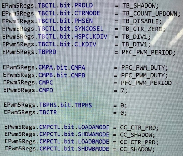
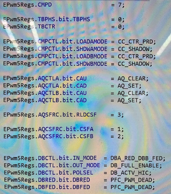
Below are their configuration.

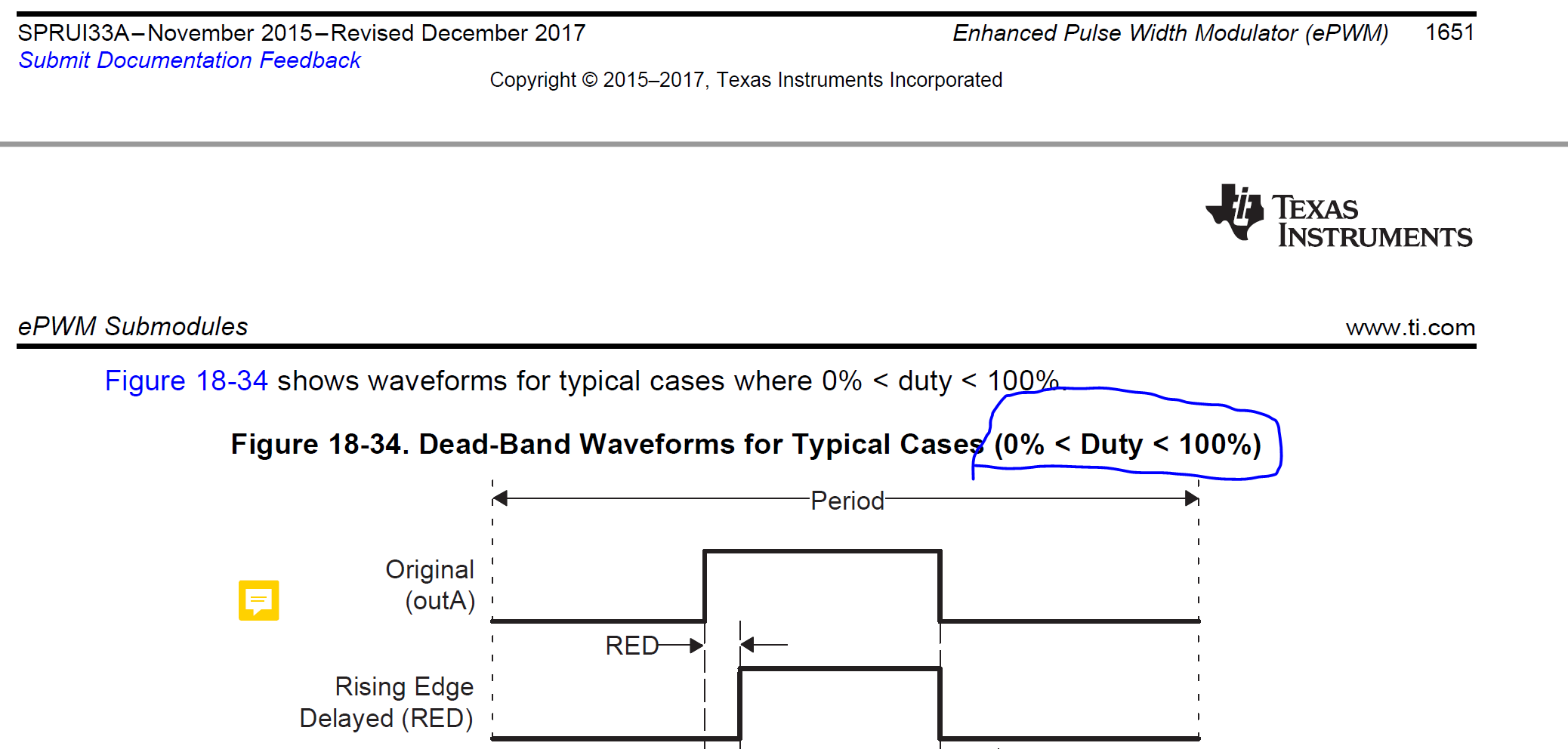
BTW, could you if below page on datasheet including duty equals zero condition?

Thanks

Sheldon

  • I believe using deadband with  the 0% duty is a limitation. I will get back to you with a definitive answer.

  • Hi Nima,

    Any updates then?

    Thanks

  • Okay after a lot of digging, I found this code I had written a while back. This uses 100% duty and 0% duty with deadband can you have them try it while I check for the deadband limitation?

    //###########################################################################
    //
    // FILE:    epwm_deadband_c28.c
    //
    // TITLE:   Check PWM Dead-Band
    //
    //! \addtogroup cpu01_example_list
    //! <h1> EPWM dead band control (epwm_deadband)</h1>
    //!
    //! During the test, monitor ePWM1, ePWM2, and/or ePWM3 outputs
    //! on a scope.
    //!
    //! - ePWM1A is on GPIO0
    //! - ePWM1B is on GPIO1
    //! - ePWM2A is on GPIO2
    //! - ePWM2B is on GPIO3
    //! - ePWM3A is on GPIO4
    //! - ePWM3B is on GPIO5
    //!
    //! This example configures ePWM1, ePWM2 and ePWM3 for:
    //! - Count up/down
    //! - Deadband
    //!
    //! 3 Examples are included:
    //! - ePWM1: Active low PWMs
    //! - ePWM2: Active low complementary PWMs
    //! - ePWM3: Active high complementary PWMs
    //!
    //! Each ePWM is configured to interrupt on the 3rd zero event.
    //! When this happens the deadband is modified such that
    //! 0 <= DB <= DB_MAX.  That is, the deadband will move up and
    //! down between 0 and the maximum value.
    //!
    //! View the EPWM1A/B, EPWM2A/B and EPWM3A/B waveforms
    //! via an oscilloscope
    //
    //
    //###########################################################################
    // $TI Release: F2837xD Support Library v3.05.00.00 $
    // $Release Date: Tue Jun 26 03:15:23 CDT 2018 $
    // $Copyright:
    // Copyright (C) 2013-2018 Texas Instruments Incorporated - http://www.ti.com/
    //
    // Redistribution and use in source and binary forms, with or without
    // modification, are permitted provided that the following conditions
    // are met:
    //
    //   Redistributions of source code must retain the above copyright
    //   notice, this list of conditions and the following disclaimer.
    //
    //   Redistributions in binary form must reproduce the above copyright
    //   notice, this list of conditions and the following disclaimer in the
    //   documentation and/or other materials provided with the
    //   distribution.
    //
    //   Neither the name of Texas Instruments Incorporated nor the names of
    //   its contributors may be used to endorse or promote products derived
    //   from this software without specific prior written permission.
    //
    // THIS SOFTWARE IS PROVIDED BY THE COPYRIGHT HOLDERS AND CONTRIBUTORS
    // "AS IS" AND ANY EXPRESS OR IMPLIED WARRANTIES, INCLUDING, BUT NOT
    // LIMITED TO, THE IMPLIED WARRANTIES OF MERCHANTABILITY AND FITNESS FOR
    // A PARTICULAR PURPOSE ARE DISCLAIMED. IN NO EVENT SHALL THE COPYRIGHT
    // OWNER OR CONTRIBUTORS BE LIABLE FOR ANY DIRECT, INDIRECT, INCIDENTAL,
    // SPECIAL, EXEMPLARY, OR CONSEQUENTIAL DAMAGES (INCLUDING, BUT NOT
    // LIMITED TO, PROCUREMENT OF SUBSTITUTE GOODS OR SERVICES; LOSS OF USE,
    // DATA, OR PROFITS; OR BUSINESS INTERRUPTION) HOWEVER CAUSED AND ON ANY
    // THEORY OF LIABILITY, WHETHER IN CONTRACT, STRICT LIABILITY, OR TORT
    // (INCLUDING NEGLIGENCE OR OTHERWISE) ARISING IN ANY WAY OUT OF THE USE
    // OF THIS SOFTWARE, EVEN IF ADVISED OF THE POSSIBILITY OF SUCH DAMAGE.
    // $
    //###########################################################################
    
    //
    // Included Files
    //
    #include "F28x_Project.h"
    
    
    //
    // Function Prototypes
    //
    void InitEPwm1Example(void);
    __interrupt void epwm1_isr(void);
    //
    // Main
    //
    void main(void)
    {
    //
    // Step 1. Initialize System Control:
    // PLL, WatchDog, enable Peripheral Clocks
    // This example function is found in the F2837xD_SysCtrl.c file.
    //
        InitSysCtrl();
    
    //
    // Step 2. Initialize GPIO:
    // This example function is found in the F2837xD_Gpio.c file and
    // illustrates how to set the GPIO to its default state.
    //
    //    InitGpio();
    
    //
    // enable PWM1, PWM2 and PWM3
    //
        CpuSysRegs.PCLKCR2.bit.EPWM1=1;
    
    //
    // For this case just init GPIO pins for ePWM1, ePWM2, ePWM3
    // These functions are in the F2837xD_EPwm.c file
    //
        InitEPwm1Gpio();
    
    //
    // Step 3. Clear all interrupts and initialize PIE vector table:
    // Disable CPU interrupts
    //
        DINT;
    
    //
    // Initialize the PIE control registers to their default state.
    // The default state is all PIE interrupts disabled and flags
    // are cleared.
    // This function is found in the F2837xD_PieCtrl.c file.
    //
        InitPieCtrl();
    
    //
    // Disable CPU interrupts and clear all CPU interrupt flags:
    //
        IER = 0x0000;
        IFR = 0x0000;
    
    //
    // Initialize the PIE vector table with pointers to the shell Interrupt
    // Service Routines (ISR).
    // This will populate the entire table, even if the interrupt
    // is not used in this example.  This is useful for debug purposes.
    // The shell ISR routines are found in F2837xD_DefaultIsr.c.
    // This function is found in F2837xD_PieVect.c.
    //
        InitPieVectTable();
    
    //
    // Interrupts that are used in this example are re-mapped to
    // ISR functions found within this file.
    //
        EALLOW; // This is needed to write to EALLOW protected registers
        PieVectTable.EPWM1_INT = &epwm1_isr;
        EDIS;   // This is needed to disable write to EALLOW protected registers
    
    //
    // Step 4. Initialize the Device Peripherals:
    //
        EALLOW;
        CpuSysRegs.PCLKCR0.bit.TBCLKSYNC =0;
        EDIS;
    
        InitEPwm1Example();
    
        EALLOW;
        CpuSysRegs.PCLKCR0.bit.TBCLKSYNC =1;
        EDIS;
    
    
    //
    // Enable CPU INT3 which is connected to EPWM1-3 INT:
    //
        IER |= M_INT3;
    
    //
    // Enable EPWM INTn in the PIE: Group 3 interrupt 1-3
    //
        PieCtrlRegs.PIEIER3.bit.INTx1 = 1;
    
    //
    // Enable global Interrupts and higher priority real-time debug events:
    //
        EINT;  // Enable Global interrupt INTM
        ERTM;  // Enable Global realtime interrupt DBGM
    
    //
    // Step 6. IDLE loop. Just sit and loop forever (optional):
    //
        for(;;)
        {
            F28x_usDelay(400);
            EPwm1Regs.CMPA.bit.CMPA = 4000;
            F28x_usDelay(400);
            EPwm1Regs.CMPA.bit.CMPA = 0;
            asm ("          NOP");
        }
    }
    
    //
    // epwm1_isr - EPWM1 ISR
    //
    __interrupt void epwm1_isr(void)
    {
    
        //
        // Clear INT flag for this timer
        //
        EPwm1Regs.ETCLR.bit.INT = 1;
    
        //
        // Acknowledge this interrupt to receive more interrupts from group 3
        //
        PieCtrlRegs.PIEACK.all = PIEACK_GROUP3;
    }
    
    
    //
    // InitEPwm1Example - Initialize EPWM1 configuration
    //
    void InitEPwm1Example()
    {
        EPwm1Regs.TBPRD = 4000;                       // Set timer period
        EPwm1Regs.TBPHS.bit.TBPHS = 0x0000;           // Phase is 0
        EPwm1Regs.TBCTR = 0x0000;                     // Clear counter
    
        //
        // Setup TBCLK
        //
        EPwm1Regs.TBCTL.bit.CTRMODE = TB_COUNT_UPDOWN; // Count up
        EPwm1Regs.TBCTL.bit.PHSEN = TB_DISABLE;        // Disable phase loading
        EPwm1Regs.TBCTL.bit.HSPCLKDIV = TB_DIV4;       // Clock ratio to SYSCLKOUT
        EPwm1Regs.TBCTL.bit.CLKDIV = TB_DIV4;
    
        EPwm1Regs.CMPCTL.bit.SHDWAMODE = CC_SHADOW;    // Load registers every ZERO
        EPwm1Regs.CMPCTL.bit.SHDWBMODE = CC_SHADOW;
        EPwm1Regs.CMPCTL.bit.LOADAMODE = CC_CTR_ZERO;
        EPwm1Regs.CMPCTL.bit.LOADBMODE = CC_CTR_ZERO;
    
        //
        // Setup compare
        //
        EPwm1Regs.CMPA.bit.CMPA = 4000;
    
        //
        // Set actions
        //
        EPwm1Regs.AQCTLA.bit.CAU = AQ_SET;            // Set PWM1A on Zero
        EPwm1Regs.AQCTLA.bit.CAD = AQ_CLEAR;
    
        EPwm1Regs.AQCTLB.bit.CAU = AQ_SET;          // Set PWM1A on Zero
        EPwm1Regs.AQCTLB.bit.CAD = AQ_CLEAR;
    
        //
        // Active Low PWMs - Setup Deadband
        //
        EPwm1Regs.DBCTL.bit.OUT_MODE = DB_FULL_ENABLE;
        EPwm1Regs.DBCTL.bit.POLSEL = DB_ACTV_LO;
        EPwm1Regs.DBCTL.bit.IN_MODE = DBA_ALL;
        EPwm1Regs.DBRED.bit.DBRED = 0x3F0;
        EPwm1Regs.DBFED.bit.DBFED = 0x3F0;
    
        //
        // Interrupt where we will change the Deadband
        //
        EPwm1Regs.ETSEL.bit.INTSEL = ET_CTR_ZERO;    // Select INT on Zero event
        EPwm1Regs.ETSEL.bit.INTEN = 1;               // Enable INT
        EPwm1Regs.ETPS.bit.INTPRD = ET_3RD;          // Generate INT on 3rd event
    }
    
    
    //
    // End of file
    //

  • After searching for a limitation on duty and deadband, I still havent been able to find one. I tested the code above and it functions as expected. I will let you know if I find anything that states otherwise.

    Nima

  • Hi Nima,

    Thanks for your code. I will have a try and discuss with my customer.

    Please let me know if any updates from your side.

    Thanks

    Shedlon