Other Parts Discussed in Thread: DRV8312, C2000WARE
Hello,
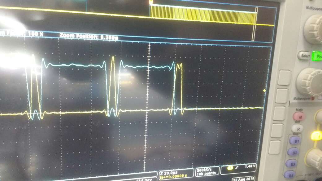
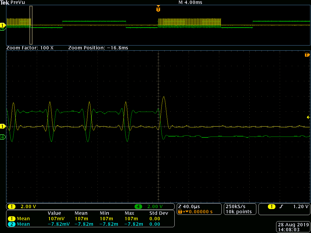
I am using driver IC UCC27201AQDDARQ1 with transistor to drive BLDC motor, I have changed the code BLDC_Censored which is for DRV8312 for the dead band, My problem is there is a slight overlap between ePWMA and ePWMB at the end, please let me know if there is some mistake in code. I am attaching code and waveforms here.
#define DEAD_BAND 10
#define OUT_MODE_ENABLE 3
#define IN_MODE_EPWMA 0
EPwm1Regs.DBCTL.bit.OUT_MODE = OUT_MODE_ENABLE;
EPwm2Regs.DBCTL.bit.OUT_MODE = OUT_MODE_ENABLE;
EPwm3Regs.DBCTL.bit.OUT_MODE = OUT_MODE_ENABLE;
EPwm1Regs.DBCTL.bit.POLSEL = 2;
EPwm2Regs.DBCTL.bit.POLSEL = 2;
EPwm3Regs.DBCTL.bit.POLSEL = 2;
EPwm1Regs.DBCTL.bit.IN_MODE = IN_MODE_EPWMA;
EPwm2Regs.DBCTL.bit.IN_MODE = IN_MODE_EPWMA;
EPwm3Regs.DBCTL.bit.IN_MODE = IN_MODE_EPWMA;
EPwm1Regs.DBRED = DEAD_BAND;
EPwm1Regs.DBFED = DEAD_BAND;
EPwm2Regs.DBRED = DEAD_BAND;
EPwm2Regs.DBFED = DEAD_BAND;
EPwm3Regs.DBRED = DEAD_BAND;
EPwm3Regs.DBFED = DEAD_BAND;
#define BLDCPWM_MACRO(v) /* */\
/* Convert "Period" (Q15) modulation function to Q0 */\
Tmp = (int32)v.PeriodMax*(int32)v.MfuncPeriod; /* Q15 = Q0xQ15 */\
Period = (int16)(Tmp>>15); /* Q15 -> Q0 (Period) */\
/* */\
/* Check PwmActive setting */\
if (v.PwmActive==1) /* PWM active high */\
{ /* */\
GPR0_BLDC_PWM = 0x7FFF - v.DutyFunc; /* */\
CMPB_SMPL_POINT = 0x7FFF - (v.DutyFunc >> 1); /* Sample in center of PWM pulse using CMPB */\
} /* */\
/* */\
else if (v.PwmActive==0) /* PWM active low */\
{ /* */\
GPR0_BLDC_PWM = v.DutyFunc; /* */\
CMPB_SMPL_POINT = v.DutyFunc >> 1; /* Sample in center of PWM pulse using CMPB */\
} /* */\
/* */\
/* Convert "DutyFunc" or "GPR0_BLDC_PWM" (Q15) duty modulation function to Q0 */\
Tmp = (int32)Period*(int32)GPR0_BLDC_PWM; /* Q15 = Q0xQ15 */\
Tmp2 = (int32)Period*(int32)CMPB_SMPL_POINT; /* Q15 = Q0xQ15 */\
/*EPwm1Regs.CMPB = (int16)(Tmp2>>15);*/ /* Sample in center of PWM pulse using CMPB */\
/* */\
/* State s1: current flows to motor windings from phase A->B, de-energized phase = C */\
if (v.CmtnPointer==0) /* */\
{ /* */\
EPwm1Regs.AQCSFRC.bit.CSFB = 0; /* Forcing disabled on output B of EPWM1 */\
EPwm1Regs.AQCSFRC.bit.CSFA = 0; /* Forcing disabled on output A of EPWM1 */\
EPwm1Regs.AQCTLA.bit.CAU = 2; /* Set high when CTR = CMPA on UP-count */\
EPwm1Regs.AQCTLA.bit.ZRO = 1; /* Set low when CTR = Zero */\
EPwm1Regs.AQCTLB.bit.CAU = 1; /* Set low when CTR = Zero */\
EPwm1Regs.AQCTLB.bit.ZRO = 2; /* Set high when CTR = CMPA on UP-count */\
EPwm1Regs.CMPA.half.CMPA = (int16)(Tmp>>15); /* PWM signal on output B of EPWM1 (Q15 -> Q0) */\
/*EPwm1Regs.AQCSFRC.bit.CSFA = 2;*/ /* Forcing a continuous High on output A of EPWM1 */\
/* */\
EPwm2Regs.AQCSFRC.bit.CSFA = 1; /* Forcing a continuous Low on output A of EPWM2 */\
/*EPwm2Regs.AQCSFRC.bit.CSFB = 2; Forcing a continuous High on output B of EPWM2 */\
/* */\
EPwm3Regs.AQCSFRC.bit.CSFA = 1; /* Forcing a continuous Low on output A of EPWM3 */\
EPwm3Regs.AQCSFRC.bit.CSFB = 1; /* Forcing a continuous Low on output B of EPWM3 */\
EPwm1Regs.DBCTL.bit.OUT_MODE = 3; \
EPwm2Regs.DBCTL.bit.OUT_MODE = 3; \
EPwm3Regs.DBCTL.bit.OUT_MODE = 0; \
} /* */\
/* */\
/* State s2: current flows to motor windings from phase A->C, de-energized phase = B */\
else if (v.CmtnPointer==1) /* */\
{ /* */\
EPwm1Regs.AQCSFRC.bit.CSFB = 0; /* Forcing disabled on output B of EPWM1 */\
EPwm1Regs.AQCSFRC.bit.CSFA = 0; /* Forcing disabled on output A of EPWM1 */\
EPwm1Regs.AQCTLA.bit.CAU = 2; /* Set high when CTR = CMPA on UP-count */\
EPwm1Regs.AQCTLA.bit.ZRO = 1; /* Set low when CTR = Zero */\
EPwm1Regs.AQCTLB.bit.CAU = 1; /* Set low when CTR = Zero */\
EPwm1Regs.AQCTLB.bit.ZRO = 2; /* Set high when CTR = CMPA on UP-count */\
EPwm1Regs.CMPA.half.CMPA = (int16)(Tmp>>15); /* PWM signal on output B of EPWM1 (Q15 -> Q0) */\
/*EPwm1Regs.AQCSFRC.bit.CSFA = 2;*/ /* Forcing a continuous High on output A of EPWM1 */\
/* */\
EPwm2Regs.AQCSFRC.bit.CSFA = 1; /* Forcing a continuous Low on output A of EPWM2 */\
EPwm2Regs.AQCSFRC.bit.CSFB = 1; /* Forcing a continuous Low on output B of EPWM2 */\
/* */\
EPwm3Regs.AQCSFRC.bit.CSFA = 1; /* Forcing a continuous Low on output A of EPWM3 */\
/*EPwm3Regs.AQCSFRC.bit.CSFB = 2; Forcing a continuous High on output B of EPWM3 */\
EPwm1Regs.DBCTL.bit.OUT_MODE = 3; \
EPwm2Regs.DBCTL.bit.OUT_MODE = 0; \
EPwm3Regs.DBCTL.bit.OUT_MODE = 3; \
} /* */\
/* */\
/* State s3: current flows to motor windings from phase B->C, de-energized phase = A */\
else if (v.CmtnPointer==2) /* */\
{ /* */\
EPwm1Regs.AQCSFRC.bit.CSFA = 1; /* Forcing a continuous Low on output A of EPWM1 */\
EPwm1Regs.AQCSFRC.bit.CSFB = 1; /* Forcing a continuous Low on output B of EPWM1 */\
/* */\
EPwm2Regs.AQCSFRC.bit.CSFB = 0; /* Forcing disabled on output B of EPWM2 */\
EPwm2Regs.AQCSFRC.bit.CSFA = 0; /* Forcing disabled on output A of EPWM2 */\
EPwm2Regs.AQCTLA.bit.CAU = 2; /* Set high when CTR = CMPA on UP-count */\
EPwm2Regs.AQCTLA.bit.ZRO = 1; /* Set low when CTR = Zero */\
EPwm2Regs.AQCTLB.bit.CAU = 1; /* Set low when CTR = Zero */\
EPwm2Regs.AQCTLB.bit.ZRO = 2; /* Set high when CTR = CMPA on UP-count */\
EPwm2Regs.CMPA.half.CMPA = (int16)(Tmp>>15); /* PWM signal on output B of EPWM2 (Q15 -> Q0) */\
/*EPwm2Regs.AQCSFRC.bit.CSFA = 2;*/ /* Forcing a continuous High on output A of EPWM2 */\
/* */\
EPwm3Regs.AQCSFRC.bit.CSFA = 1; /* Forcing a continuous Low on output A of EPWM3 */\
/*EPwm3Regs.AQCSFRC.bit.CSFB = 2; Forcing a continuous High on output B of EPWM3 */\
EPwm1Regs.DBCTL.bit.OUT_MODE = 0; \
EPwm2Regs.DBCTL.bit.OUT_MODE = 3; \
EPwm3Regs.DBCTL.bit.OUT_MODE = 3; \
} /* */\
/* */\
/* State s4: current flows to motor windings from phase B->A, de-energized phase = C */\
else if (v.CmtnPointer==3) /* */\
{ /* */\
EPwm1Regs.AQCSFRC.bit.CSFA = 1; /* Forcing a continuous Low on output A of EPWM1 */\
/*EPwm1Regs.AQCSFRC.bit.CSFB = 2; Forcing a continuous High on output B of EPWM1 */\
/* */\
EPwm2Regs.AQCSFRC.bit.CSFB = 0; /* Forcing disabled on output B of EPWM2 */\
EPwm2Regs.AQCSFRC.bit.CSFA = 0; /* Forcing disabled on output A of EPWM2 */\
EPwm2Regs.AQCTLA.bit.CAU = 2; /* Set high when CTR = CMPA on UP-count */\
EPwm2Regs.AQCTLA.bit.ZRO = 1; /* Set low when CTR = Zero */\
EPwm2Regs.AQCTLB.bit.CAU = 1; /* Set low when CTR = Zero */\
EPwm2Regs.AQCTLB.bit.ZRO = 2; /* Set high when CTR = CMPA on UP-count */\
EPwm2Regs.CMPA.half.CMPA = (int16)(Tmp>>15); /* PWM signal on output B of EPWM2 (Q15 -> Q0) */\
/*EPwm2Regs.AQCSFRC.bit.CSFA = 2;*/ /* Forcing a continuous High on output A of EPWM2 */\
/* */\
EPwm3Regs.AQCSFRC.bit.CSFA = 1; /* Forcing a continuous Low on output A of EPWM3 */\
EPwm3Regs.AQCSFRC.bit.CSFB = 1; /* Forcing a continuous Low on output B of EPWM3 */\
EPwm1Regs.DBCTL.bit.OUT_MODE = 3; \
EPwm2Regs.DBCTL.bit.OUT_MODE = 3; \
EPwm3Regs.DBCTL.bit.OUT_MODE = 0; \
} /* */\
/* */\
/* State s5: current flows to motor windings from phase C->A, de-energized phase = B */\
else if (v.CmtnPointer==4) /* */\
{ /* */\
EPwm1Regs.AQCSFRC.bit.CSFA = 1; /* Forcing a continuous Low on output A of EPWM1 */\
/*EPwm1Regs.AQCSFRC.bit.CSFB = 2; Forcing a continuous High on output B of EPWM1 */\
/* */\
EPwm2Regs.AQCSFRC.bit.CSFA = 1; /* Forcing a continuous Low on output A of EPWM2 */\
EPwm2Regs.AQCSFRC.bit.CSFB = 1; /* Forcing a continuous Low on output B of EPWM2 */\
/* */\
EPwm3Regs.AQCSFRC.bit.CSFB = 0; /* Forcing disabled on output B of EPWM3 */\
EPwm3Regs.AQCSFRC.bit.CSFA = 0; /* Forcing disabled on output A of EPWM3 */\
EPwm3Regs.AQCTLA.bit.CAU = 2; /* Set high when CTR = CMPA on UP-count */\
EPwm3Regs.AQCTLA.bit.ZRO = 1; /* Set low when CTR = Zero */\
EPwm3Regs.AQCTLB.bit.CAU = 1; /* Set low when CTR = Zero */\
EPwm3Regs.AQCTLB.bit.ZRO = 2; /* Set high when CTR = CMPA on UP-count */\
EPwm3Regs.CMPA.half.CMPA = (int16)(Tmp>>15); /* PWM signal on output B of EPWM3 (Q15 -> Q0) */\
/*EPwm3Regs.AQCSFRC.bit.CSFA = 2;*/ /* Forcing a continuous High on output A of EPWM3 */\
EPwm1Regs.DBCTL.bit.OUT_MODE = 3; \
EPwm2Regs.DBCTL.bit.OUT_MODE = 0; \
EPwm3Regs.DBCTL.bit.OUT_MODE = 3; \
} /* */\
/* */\
/* State s6: current flows to motor windings from phase C->B, de-energized phase = A */\
else if (v.CmtnPointer==5) /* */\
{ /* */\
EPwm1Regs.AQCSFRC.bit.CSFA = 1; /* Forcing a continuous Low on output A of EPWM1 */\
EPwm1Regs.AQCSFRC.bit.CSFB = 1; /* Forcing a continuous Low on output B of EPWM1 */\
/* */\
EPwm2Regs.AQCSFRC.bit.CSFA = 1; /* Forcing a continuous Low on output A of EPWM2 */\
/*EPwm2Regs.AQCSFRC.bit.CSFB = 2; Forcing a continuous High on output B of EPWM2 */\
/* */\
EPwm3Regs.AQCSFRC.bit.CSFB = 0; /* Forcing disabled on output B of EPWM3 */\
EPwm3Regs.AQCSFRC.bit.CSFA = 0; /* Forcing disabled on output A of EPWM3 */\
EPwm3Regs.AQCTLA.bit.CAU = 2; /* Set high when CTR = CMPA on UP-count */\
EPwm3Regs.AQCTLA.bit.ZRO = 1; /* Set low when CTR = Zero */\
EPwm3Regs.AQCTLB.bit.CAU = 1; /* Set low when CTR = Zero */\
EPwm3Regs.AQCTLB.bit.ZRO = 2; /* Set high when CTR = CMPA on UP-count */\
EPwm3Regs.CMPA.half.CMPA = (int16)(Tmp>>15); /* PWM signal on output B of EPWM3 (Q15 -> Q0) */\
/*EPwm3Regs.AQCSFRC.bit.CSFA = 2;*/ /* Forcing a continuous High on output A of EPWM3 */\
EPwm1Regs.DBCTL.bit.OUT_MODE = 0; \
EPwm2Regs.DBCTL.bit.OUT_MODE = 3; \
EPwm3Regs.DBCTL.bit.OUT_MODE = 3; \
}