This thread has been locked.

If you have a related question, please click the "Ask a related question" button in the top right corner. The newly created question will be automatically linked to this question.

TMS320F28069M: Bootloader for Firmware Update Using Serial Port between PC and F28069

Part Number: TMS320F28069M
Other Parts Discussed in Thread: DRV8305, C2000WARE, CONTROLSUITE

Dear Sir or Madam,

I built a bootloader for firmware update between PC and TI 28069 using UART serial port. I have couple questions after I finished built this bootloader:

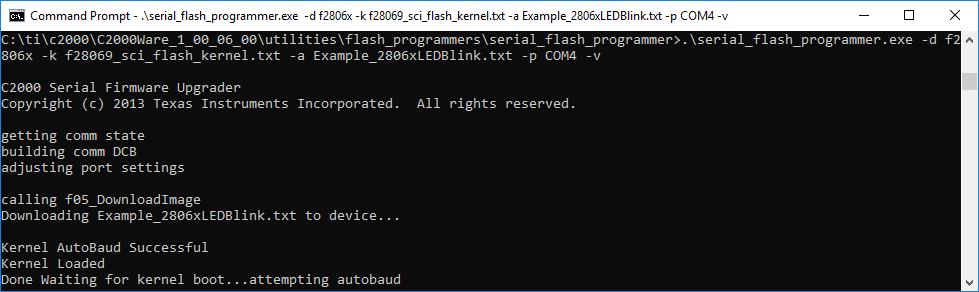
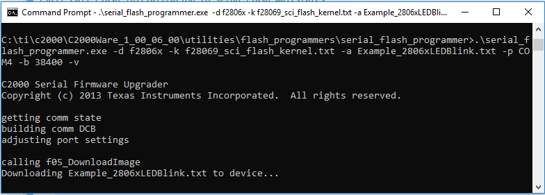
1. If I just used 28069 Launchpad run the bootloader, everything is OK

the output on the prompt was as below:

Then I plugged DRV8305 board on the 28069 Launchpad, and add 12 VDC power to PVDD. the D1 LED (Red), nFAULT, on. The same bootloader couldn't finish to run. It stopped on "Downloading .txt to device..." as below, How can I solve this problem?

2. If I use serial flash bootloader to update the firmware, I need set up the switch S1 on F28069M Launchpad to 100. After I finish the firmware update, I need change it back to 111. If our product wrap up in the frame, it will be very difficult to access the switch S1. Does any good solution for this situation?

Thank you,

Hao

  • Hao

    1) Make sure you are following the same procedure and that the device is in the ROM SCI bootloader. Also check that the device isn't resetting. You load the boot symbols to confirm your location in boot ROM via CCS. Load .OUT file at ~/C2000Ware_2_00_00_02\libraries\boot_rom\f2806x\v1_1\rom_sources\Release

    2) If you don't plan on using boot mode select pins to switch boot modes, then you should set it to GetMode with boot to flash and then put your own bootloader in the flash. The ROM SCI bootloader source code is located in C2000Ware

    Best regards

    Chris

  • Dear Sir,

    I wnat to set "Boot Mode Selected" to GetMode with boot to SCI. I go through the steps as below:

    1. I first set up the switch S1 on f28069 Launchpad to 101 to choose "Boot Mode Selected" to GetMode with boot to SCI.

    2. I then go to the folder C:\ti\c2000\C2000Ware_1_00_06_00\device_support\f2806x\examples\c28\f28069_sci_flash_kernel to build the serial flash kernel file, kern.out.

    3. Then I go to the folder C:\ti\c2000\C2000Ware_1_00_06_00\device_support\f2806x\examples\c28\timed_led_blink to build the application file, app.out. Before, I need change its cmd file from RAM to flash.

    4. Next, I go to C:\ti\ccs901\ccs\tools\compiler\ti-cgt-c2000_18.12.1.LTS\bin to generate the stream flow files kern.txt from kern.out and app.txt from app.out.

    5. Finally, I got to the folder C:\ti\c2000\C2000Ware_1_00_06_00\utilities\flash_programmers\serial_flash_programmer, and use the command below to download the kernel and application to f28069 flash via SCI.
    .\serial_flash_programmer.exe -d f2806x -k f28069_sci_flash_kernel.txt -a SChaeffler_F28069.txt -p COM4

    The same bootloader couldn't finish to run. It stopped on "Downloading .txt to device..." as below.

    Do I miss something for GetMode with boot to SCI? How can I set up OTP_BMODE to 0x0001 which is GetMode with boot to SCI? What folder is the SCI flash kernel for F28069 in C2000 or ControlSuite?

    Thanks,

    Hao

  • Hao

    GetBoot won't boot to SCI without first programming the OTP. For now, I recommend using the emulation configuration, refer to the "Bootloader Modes" section in the technical reference manual.

    Additionally, my recommendation of GetBoot earlier is to leave it with unprogrammed OTP, which will default to flash boot. In flash, then you can put a custom checker to determine if you want to go to your SCI bootloader or to your application.

    Setup the EMU to boot to SCI, then reset via CCS to go into boot. Use the symbols I recommended earlier to confirm that you are in SCI boot. Once in there, then it should work as expected. If not, then I'll have to get an expert in regards to your booster pack.

    Best regards

    Chris

  • Chris,

    It looks like the bootloader always jumps to the entrypoint of flash not to the entrypoint of sci. Should I add a call function and maybe some library to branch to sci. If so, can you let me know how I can add a call in sci boot and main function? How can I "Setup the EMU to boot to SCI, then reset via CCS to go into boot."? What symbol I can use to confirm it is in sci?

    Thank you much,

    Hao

  • Hao

    If the SCI bootloader isn't properly receiving the key, it will return the flash entry point instead of the application entry point.

    The SCI bootloader in ROM is located at address 0x003ff697

    Use my instructions in my first post on how to load symbols so you can step through and debug while in ROM code.

    Follow the instructions in the technical reference manual to configure emulation boot values for SCI and then you use the reset CPU button in CCS to go to the start of boot.

    Best regards

    Chris

  • Chris,

    1. Where can I set the SCI bootloader in ROM at address 0x003ff697 as you said, in a cmd file or other c source file?

    2. What c source file can I configure emulation boot values for SCI like EMU_KEY = 0x55AA, and EMU_BMODE = 0x0001?

    3. When I set the switch S1 on f28069 Launchpad to 110 to choose "Boot Mode Selected" to GetMode with boot to SCI as the technical reference manual, I cannot access to symbols and reset CPU button in CCS with XDS100v2. How can I solve it?

    Thanks,

    Hao

  • Hao

    1. That is the address of the SCI bootloader function in ROM. You can use that address to setup a function call to that address in your code where the prototype will be "Uint32 SCI_Boot()". Then you can run the SCI bootloader from your app and it will return the entry address of the loaded application. 

    2. I suggest just modifying the EMU values from the CCS memory browser when debugging. EMU key is at address 0xD00 and EMUBMODE is at address 0xD01

    3. I believe you are disabling the JTAG TRST, which you need enabled for debugging. Keep that set to 1 when debugging and not doing standalone.

    Best regards

    Chris

  • Chris,

    I cannot modifying the EMU values from the CCS memory browser or expressions when debugging. It sounds like these emulation psuedo registers cannot be changed in CCS memory browser or expressions when debugging? If it is true, how can I change these EMU values?

    Thanks,

    Hao

  • Hao

    Interesting. They can definitely be configured via the CCS memory browser.
    Likely an issue in the GEL file.

    When connected to the device, in CCS go to tools->Gel and open the GEL file. Locate the F28069_Memory_Map() function and add the following line at bottom of function.
    GEL_MapAdd(0xd00,1,0x100,1,1);

    Best regards
    Chris

  • Chris,

    When I use GetMode, I need also change the values of OTP like OTP KEY. But I cannot modify these OTP values. I try to do it in GEL file but not working. Can you let me know how I can change these OTP values?

    Thank you,

    Hao

  • Chris,

    I go to the folder, f28069_sci_flash_kernel to build the serial flash kernel file, kern.out. Then I go to the folder, timed_led_blink to build the application file, app.out. Next, I generate the stream flow files kern.txt from kern.out and app.txt from app.out. Finally, I use the command below to download the kernel and application to f28069 flash via SCI:
    .\serial_flash_programmer.exe -d f2806x -k f28069_sci_flash_kernel.txt -a SChaeffler_F28069.txt -p COM4

    After that, I set up the switch S1 on f28069 Launchpad to 101 (GPIO37 GPIO34 TRSTn) to EMU Mode. Then I go to debug. and set up EmuKey to 0x55AA and EmuBMode to 0x0001 to select Boot Mode to SCI. Finally, I reset by Reset->CPU Reset.

    But The same bootloader couldn't finish to run. It stopped on "Downloading Example_2806xLEDBlink.txt to device..." as below.

    Can I still use the same command to load the kernel.txt and application.txt below?

    .\serial_flash_programmer.exe -d f2806x -k f28069_sci_flash_kernel.txt -a Example_2806xLEDBlink.txt -p COM4

    and then set EmuKey and EmuBMode, and reset CPU as you said?

    Thanks,

    Hao 

  • Hao

    You can program the OTP via the CCS flash utility (Tools -> On-chip flash).

    You should connect to the device, set the EMU values, reset the CPU,and run/resume. This will place you in the bootloader, now run the command. That command looks correct.

    Best regards

    Chris

  • Chris,

    I set up the switch S1 on f28069 Launchpad to 111 (GPIO37 GPIO34 TRSTn) to EMU Mode. Then I followed steps as you mentioned as above. But The same bootloader couldn't finish to run. It stopped on "Done Waiting for kernel boot...attempting autobaud" as below.

    I don't know what causes it stop and how I can solve it? Should I change the call of Uint32 SCI_Boot() in the application?

    I have a more question: Is there any way to program and change the values of OTP key and OTP BMode?

    Thanks,

    Hao

  • Hao

    Make sure the kernel is setup to use the same SCI GPIOs that you're using for the bootloader.

    The OTP key and BMODE are one time programmable, you can only program them once. You can program the OTP via the CCS flash utility (Tools -> On-chip flash).

    Best regards

    Chris

  • Chris,

    I didn't change anything including the kernel's setting of SCI GPIOs. I used all the same command and the stream files for kernel and application. But The same bootloader couldn't finish to run. It stopped on "Done Waiting for kernel boot...attempting autobaud". Do you think if there is anything else I need do?

    Thanks,

    Hao

  • Hao

    If you halt and load symbols for the kernel app when you get stuck, is the app in the kernel waiting for autobaud (to then receive the LED app)?

    I've seen instances where HBAUD needs to be cleared, which current kernel doesn't do. You can add in SciaRegs.SCIHBAUD = 0 in the kernel.

    Best regards

    Chris

  • Chris,

    I have a question:

    if our product doesn't allow to exist a JTAG/miniUSB port due to cost and space, we can not use Emulation Boot modes anymore. What is the best boot mode we can use for like CAN bootloader? Should we only use Stand-Alone Boot Modes with GetMode: CAN? If so, we can only program for OTP Key to 0x005A and OTP BMode to 0x0007.

    I try to program in the main function as below:

     (*OTP_KEY) = 0x005A;
     (*OTP_BMODE) = 0x0007;

    I received the error message as below when I compiled it:

    How can I program to set up OTP Key and OTP BMode values?

    Thanks,

    Hao

  • Hao

    Yes, if you want CAN boot every time, then program OTP for CAN boot. However, the CAN bootloader won't timeout. If at some point you want to skip the CAN bootloader, a CAN bus must be connected and transit invalid key.

    I typically always recommend to set your bootmode to boot to flash and put the bootloader as part of your application so you can have your own decision logic to use the bootloader or run the flash application.

    For programming OTP, it is easiest to setup a const variable with a pragma to the address location (defined in the linker command file).

    Refer to this example on regarding use of the DATA_SECTION pragma: ~\C2000Ware_2_00_00_02\device_support\f2806x\examples\c28\dma_ram_to_ram

    Best regards

    Chris