Other Parts Discussed in Thread: C2000WARE
Tool/software: Code Composer Studio
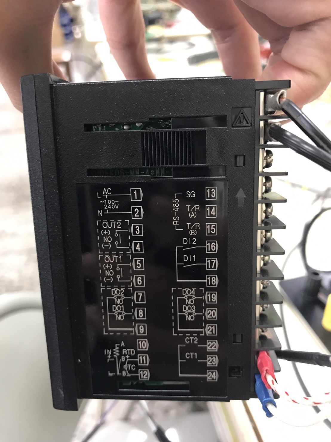
I use this code to send my chart to Digital temperature Controller(RB900) but it cant work ,
I think it is baud problem but I follow other people do,
it still show original chart ,
This is I want to send char SendChar[8]={0x0001, 0x0003, 0x0000, 0x0000, 0x0000, 0x0001, 0x0084, 0x000A};
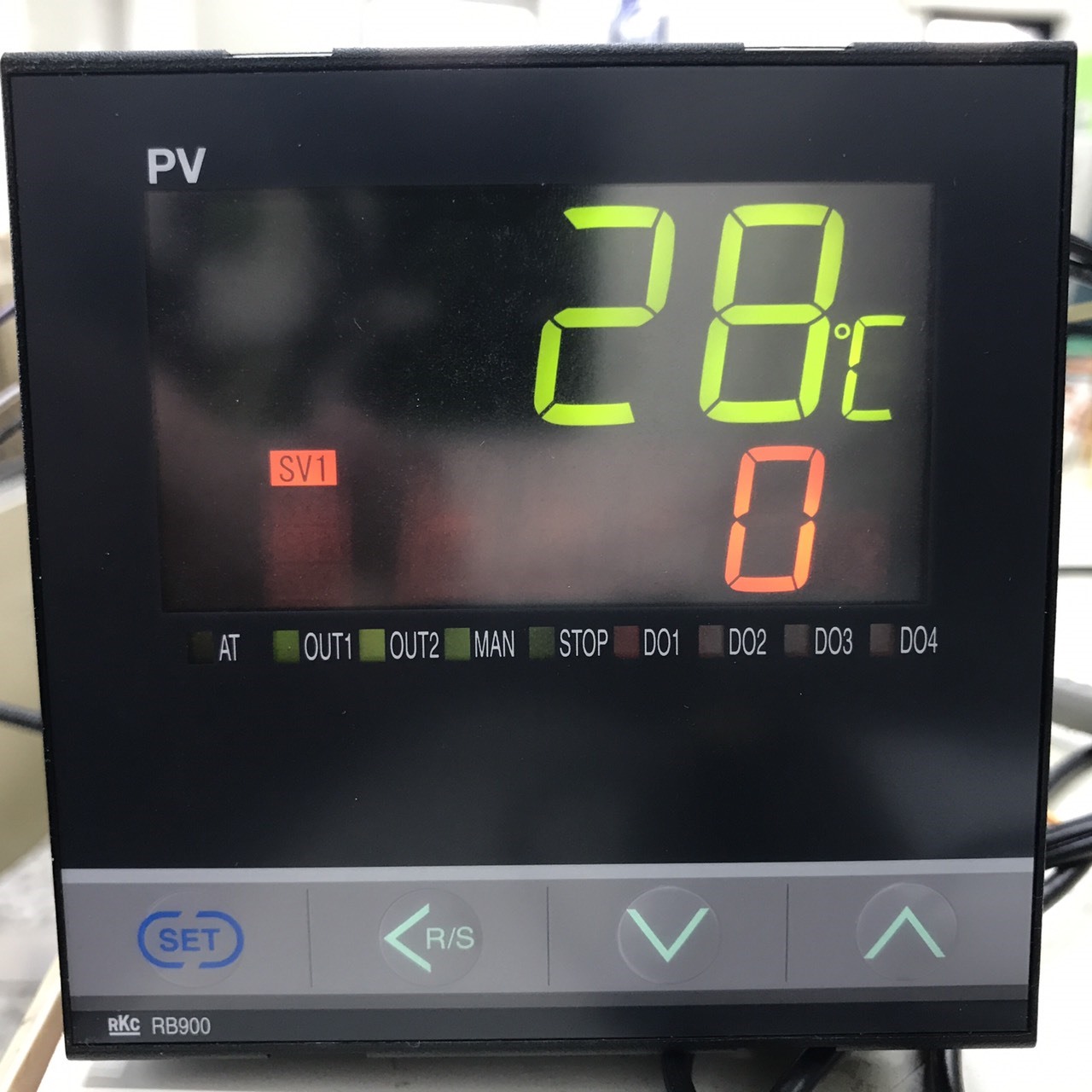
If Digital temperature Controller(RB900) show 28 degree
and I want to receive {0x0001, 0x0003, 0x0002, 0x0000, 0x001c, 0x00B9,0x008D}
Code :
#include <stdio.h>
#include "DSP28x_Project.h" // Device Headerfile and Examples Include File
void scia_loopback_init(void);
void scia_fifo_init(void);
void InitEPwm1(void);
void Gpio_Setup(void);
Uint16 LoopCount;
char SendChar[8]={0x0001, 0x0003, 0x0000, 0x0000, 0x0000, 0x0001, 0x0084, 0x000A};
char ReceivedChar[8];
int F,A,i,j;
void main(void)
{
InitSysCtrl();
InitEPwm1Gpio();
InitSciGpio();//初始化SCI引脚
EALLOW;
GpioCtrlRegs.GPAMUX1.bit.GPIO0=1; //GPIO配置為ePWM1A功能
GpioCtrlRegs.GPAMUX1.bit.GPIO1=1; //GPIO1配置為ePWM1B功能
//GpioCtrlRegs.GPAMUX1.bit.GPIO12=1; //TZ1 - Trip zone 1
//GpioCtrlRegs.GPAMUX2.bit.GPIO16=3; //TZ5 - Trip zone 5
EDIS;
EALLOW;
/* Enable internal pull-up for the selected pins */
// Pull-ups can be enabled or disabled disabled by the user.
// This will enable the pullups for the specified pins.
GpioCtrlRegs.GPAPUD.bit.GPIO28 = 0; // Enable pull-up for GPIO28 (SCIRXDA)
GpioCtrlRegs.GPAPUD.bit.GPIO29 = 0; // Enable pull-up for GPIO29 (SCITXDA)
/* Set qualification for selected pins to asynch only */
// Inputs are synchronized to SYSCLKOUT by default.
// This will select asynch (no qualification) for the selected pins.
GpioCtrlRegs.GPAQSEL2.bit.GPIO28 = 3; // Asynch input GPIO28 (SCIRXDA)
/* Configure SCI-A pins using GPIO regs*/
// This specifies which of the possible GPIO pins will be SCI functional pins.
GpioCtrlRegs.GPAMUX2.bit.GPIO28 = 1; // Configure GPIO28 for SCIRXDA operation
GpioCtrlRegs.GPAMUX2.bit.GPIO29 = 1; // Configure GPIO29 for SCITXDA operation
EDIS;
DINT;
IER = 0x0000;
IFR = 0x0000;
InitPieVectTable();
PieCtrlRegs.PIECTRL.bit.ENPIE = 1;//使能PIE
PieCtrlRegs.PIEACK.all = 0xFFFF;//写1清零,允许所有PIE都能被响应
EINT;//开启总中断
LoopCount = 0;
scia_fifo_init(); // Initialize the SCI FIFO
scia_loopback_init(); // Initalize SCI for digital loop back
InitEPwm1();
for(;;)
{
DELAY_US(1000000);
//将要发送的数据存入SCITXBUF
for(i=1;i<8;i++)
{
SciaRegs.SCITXBUF = SendChar[i];
}
//等待发送完成
while(SciaRegs.SCIFFRX.bit.RXFFST>0)
{
} // wait for RRDY/RXFFST =1 for 1 data available in FIFO
//存储接收数据
for(i=1;i<8;i++)
{
ReceivedChar[i]= SciaRegs.SCIRXBUF.all;
}
A=ReceivedChar[5]/10;
if(A==1)
{
F=2000;
}
else
{
F=2500;
}
LoopCount++;
}
}
void InitEPwm1(void)
{
EPwm1Regs.CMPA.half.CMPA=F/2;
EPwm1Regs.CMPB=F/2;
// Setup TBCLK
EPwm1Regs.TBPRD =F; // TBPRD=150M/f-1
EPwm1Regs.TBPHS.half.TBPHS = 0x0000; // Phase is 0 (相位為0)
EPwm1Regs.TBCTR = 0; //时基计数器清0
EPwm1Regs.TBCTL.bit.CTRMODE = TB_COUNT_UP; // Count up
EPwm1Regs.TBCTL.bit.PHSEN = TB_DISABLE; // Disable phase loading
EPwm1Regs.TBCTL.bit.HSPCLKDIV = TB_DIV1; // Clock ratio to SYSCLKOUT
EPwm1Regs.TBCTL.bit.CLKDIV = TB_DIV1; //时基时钟分频 1倍分频
// Setup shadowing
EPwm1Regs.CMPCTL.bit.SHDWAMODE = CC_SHADOW; //CMPA影子装载模式
EPwm1Regs.CMPCTL.bit.SHDWBMODE = CC_SHADOW;
EPwm1Regs.CMPCTL.bit.LOADAMODE = CC_CTR_ZERO; //CTR=0 影子寄存器A装载update it
EPwm1Regs.CMPCTL.bit.LOADBMODE = CC_CTR_ZERO;
// Set actions
EPwm1Regs.AQCTLA.bit.ZRO = AQ_SET; // CTR上升至CMPA值 置1 ePWMA输出高
EPwm1Regs.AQCTLA.bit.CAU = AQ_CLEAR; // CTR下降至CMPA值 置0 ePWMA输出低
EPwm1Regs.AQCTLB.bit.ZRO = AQ_SET; // CTR上升至CMPB值 置1 ePWMB输出高
EPwm1Regs.AQCTLB.bit.CBU = AQ_CLEAR; // CTR下降至CMPB值 置0 ePWMB输出低
// Interrupt where we will change the Compare Values
EPwm1Regs.ETSEL.bit.INTSEL = ET_CTR_PRD; // Select INT on PRD event
EPwm1Regs.ETSEL.bit.INTEN = 1; // Enable INT
EPwm1Regs.ETPS.bit.INTPRD = ET_1ST; // Generate INT on 1ST event
//Set dead band
EPwm1Regs.DBCTL.bit.IN_MODE = 0; //ePWMxA是雙邊沿延時輸入源
EPwm1Regs.DBCTL.bit.OUT_MODE = 3; //使能雙邊沿沿時
EPwm1Regs.DBCTL.bit.POLSEL = 2; //ePWMxA不翻轉,ePWMxB翻轉
EPwm1Regs.DBFED =625; //100ns*150M
EPwm1Regs.DBRED =625;
//Set Trip-Zone
EALLOW;
EPwm1Regs.TZSEL.bit.OSHT1 = 1; //启用TZ1作为PWM1的错误源
EPwm1Regs.TZSEL.bit.OSHT5 = 1;
EPwm1Regs.TZCTL.bit.TZA = 2; //EPWM1A will be forced low on a trip event.
EPwm1Regs.TZCTL.bit.TZB = 2;
EPwm1Regs.TZEINT.bit.OST = 1; // Enable OST interrupt
EDIS;
}
// Step 7. Insert all local Interrupt Service Routines (ISRs) and functions here:
// Test 1,SCIA DLB, 8-bit word, baud rate 0x000F, default, 1 STOP bit, no parity
void scia_loopback_init()
{
SciaRegs.SCICCR.all =0x0007; // 1 stop bit, No loopback
//配置通讯协议 // No parity,8 char bits,
// async mode, idle-line protocol
SciaRegs.SCICTL1.all =0x0003; // enable TX, RX, internal SCICLK,
// Disable RX ERR, SLEEP, TXWAKE
SciaRegs.SCICTL2.bit.TXINTENA =1;
SciaRegs.SCICTL2.bit.RXBKINTENA =1;
SciaRegs.SCIHBAUD = 0x0001; //包德率為9600
SciaRegs.SCILBAUD = 0x00E7;
SciaRegs.SCICCR.bit.LOOPBKENA =0;
//SciaRegs.SCIFFTX.all=0xC022;
//SciaRegs.SCIFFRX.all=0x0022;
//SciaRegs.SCIFFCT.all=0x00;
SciaRegs.SCICTL1.all =0x0023;
SciaRegs.SCIFFTX.bit.TXFIFOXRESET=1;
SciaRegs.SCIFFRX.bit.RXFIFORESET=1;
}
// Initalize the SCI FIFO
void scia_fifo_init()
{
SciaRegs.SCIFFTX.all=0xE040;
SciaRegs.SCIFFRX.all=0x2044;
SciaRegs.SCIFFCT.all=0x0;
}


