This thread has been locked.

If you have a related question, please click the "Ask a related question" button in the top right corner. The newly created question will be automatically linked to this question.

CCS: ADC to detect transient detect

Other Parts Discussed in Thread: TMS320F28377D

Tool/software: Code Composer Studio

hello,

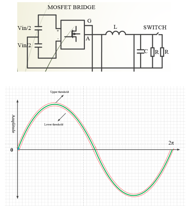
I have designed single phase inverter with pure resistive load and I have connected another load through switch, turn on and turn off switch to connect and disconnect load(Load current step up and step down). there are always two threshold levels high  threshold  and  low threshold . The 12-b A/D converters allowed for a 0.8-mV voltage resolution, the threshold voltage deviation  was set to 1.6 mV (double the least significant digit of the A/D converters).  I want to use ADC to detect  step change. ADC samples the output voltage every cycle.  If output voltage undershoot is lower than predefined  low threshold   ADC will detect step up  change (another is connected through switch ) and if output voltage overshoot is greater than high threshold then ADC will detect  step down change(another load is disconnected through switch). how can I write code for this. step change can occur at any angle. I am using TMS320F28377D.

  • Hi Shah,

    I think your 2 LSB error band is probably going to be much too tight.  Have a look at the various ADC performance specifications in the device datasheet:

    http://www.ti.com/document-viewer/TMS320F28377D/datasheet/adc-characteristics-12-bit-single-ended-mode-sprs8803422-ds-char#SPRS8803422_DS_char

    At a minimum, you'll want to use gain, offset, and linearity errors to determine the maximum deviation and then SNR to determine the noise on top of that baseline inaccuracy.  

    I'm not sure how you will write code for this specifically.  It seems like you will need to estimate the angle first, then calculate the expected conversion result, then take the expected vs actual delta and compare against your threshold specification.  

  •  I already calculated duty cycles for SPWMPOS and SPWMNEG. I just want is this right way for calculating threshold values is right way?  and vo is output voltage from sensor to ADC then i compare vo with uper and lower tresholds if output voltage is greater than or lower than these thresholds then turn on respective mode.

    // calculate sintheta from lookup table and multiply with constant value

    Vol=Vpeak_Ref*sintheta;   

    // calculate upper and lower thresholds 

    Vth_h = Vol+0.0016;             
    Vth_l = Vol-0.0016;

    // vo is outout voltage from sensor  to ADC

    if(vo>Vth_h)


    { SPWNEG(1);   // if output is greater than upper threshold then turn of SPWMNEG mode


    DELAY_US(320);


    SPWNEG(0);


    DELAY_US(110);
    }
    else


    {if(vo[2]<Vth_l)  // if output is greater than lower threshold then turn of SPWMPOS mode


    {SPWMPOS(1);


    DELAY_US(320);


    SPWMPOS(0);


    DELAY_US(120);}


    else

    SPWM(1);}

  • Hi Shah,

    I think your idea should work in general. Like Devin pointed out, you have to estimate the angle first and set the threshold accordingly. And for positive and negative cycle, the step down and step up load current will touch upper and lower threshold differently. 

    Regards,

    Chen