This thread has been locked.

If you have a related question, please click the "Ask a related question" button in the top right corner. The newly created question will be automatically linked to this question.

CCS/TMS320F28027: Multiple ADC configure in TMS320F28027 launchpad.

Part Number: TMS320F28027


Tool/software: Code Composer Studio

Hello,

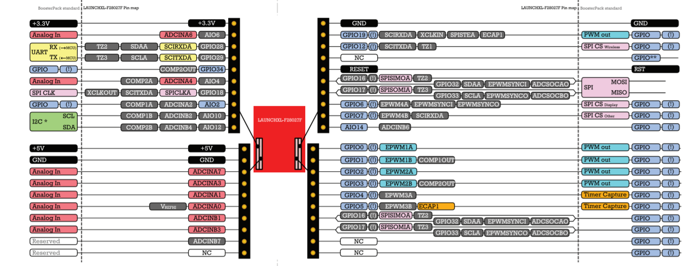
I am Sourabh working on TMS320F28027 launchpad. I am unable to configure multiple ADC inputs in TMS320F28027 board. 

Can any one suggest me how to configure it.

 I successfully configure 2 ADC as given in sample code but i need multiple ADC.

Thank you,

Sourabh 

  • Sourabh,

    First, I'd refer to the Quick Start Guide as to what ADC inputs are brought to the LP headers:

    http://www.ti.com/lit/sprz413  

    So, we have ADCIN A0/A1/A2/A3/A4/A6/A7/B1/B2/B3/B4/B6 that are available.

    Now, I beleive you are using this example ADC_SOC, which converts ADCINA2/A4  

    http://dev.ti.com/tirex/explore/node?node=AHUip0sqxJcu0jcAU7E37g__gYkahfz__LATEST 

    To add more channels, you'll need to program the ADC control logic for the other Start of Conversion(SOC) bit fields.

    You'll see this in the example:

    // set SOC0 channel select to ADCINA4
        //
        AdcRegs.ADCSOC0CTL.bit.CHSEL 	= 4;
        
        //
        // set SOC1 channel select to ADCINA4
        //
        AdcRegs.ADCSOC1CTL.bit.CHSEL 	= 4;
        
        //
        // set SOC1 channel select to ADCINA2
        //
        AdcRegs.ADCSOC2CTL.bit.CHSEL 	= 2;

    You can just continue for the channels you want(in addition to A2/A4 I assume).  For instance, if you wanted to sample ADCINB1 and ADCINB3 you would add

        // set SOC3 channel select to ADCINB1
        //
        AdcRegs.ADCSOC3CTL.bit.CHSEL 	= 9;      //ADC channel numbers are sequential, regardless of S/H A or S/H B, so ADCINB0 would be 8
        
        //
        // set SOC4 channel select to ADCINB3
        //
        AdcRegs.ADCSOC4CTL.bit.CHSEL 	= 11;


    Then you'll need to enalbe a trigger source for the new SOCs

        //
        // set SOC3 start trigger on EPWM1A, due to round-robin SOC0 converts first
        // then SOC1
        //
        AdcRegs.ADCSOC3CTL.bit.TRIGSEL 	= 5;
        
        //
        // set SOC4 start trigger on EPWM1A, due to round-robin SOC0 converts first
        // then SOC1
        //
        AdcRegs.ADCSOC4CTL.bit.TRIGSEL 	= 5;

    Finally, we need to configure the S/H window

        // set SOC3 S/H Window to 7 ADC Clock Cycles, (6 ACQPS plus 1)
        //
        AdcRegs.ADCSOC3CTL.bit.ACQPS 	= 6;
        
        //
        // set SOC4 S/H Window to 7 ADC Clock Cycles, (6 ACQPS plus 1)
        //
        AdcRegs.ADCSOC4CTL.bit.ACQPS 	= 6;
        

    All the ADC registers are orthogonal so adding more channels (up to SOC15) should be fairly straightforward from here.  You can look to change the trigger source or ACQPS later on if needed.

    This information is contained in the TRM for this device here http://www.ti.com/lit/ug/sprui09/sprui09.pdf starting on page 415

    Best,
    Matthew

  • Hello sir,

    Thank you for your valuable reply, It works great.

    Thank you,

    Sourabh