This thread has been locked.

If you have a related question, please click the "Ask a related question" button in the top right corner. The newly created question will be automatically linked to this question.

TMDSHVMTRPFCKIT: Question about TMDSHVMTRPFCKIT

Genius 3095 points

Part Number: TMDSHVMTRPFCKIT

Dear team:

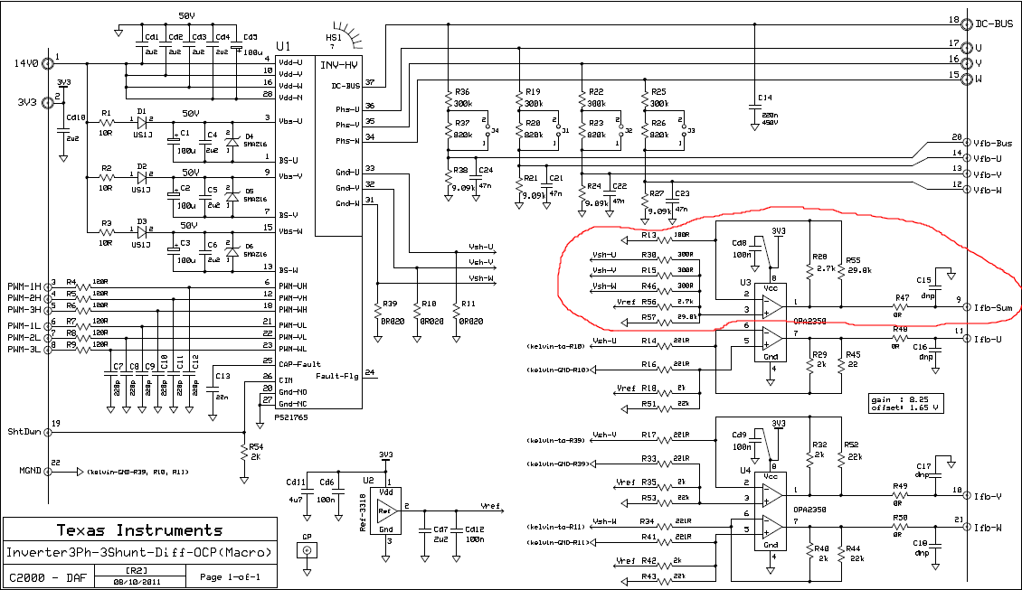
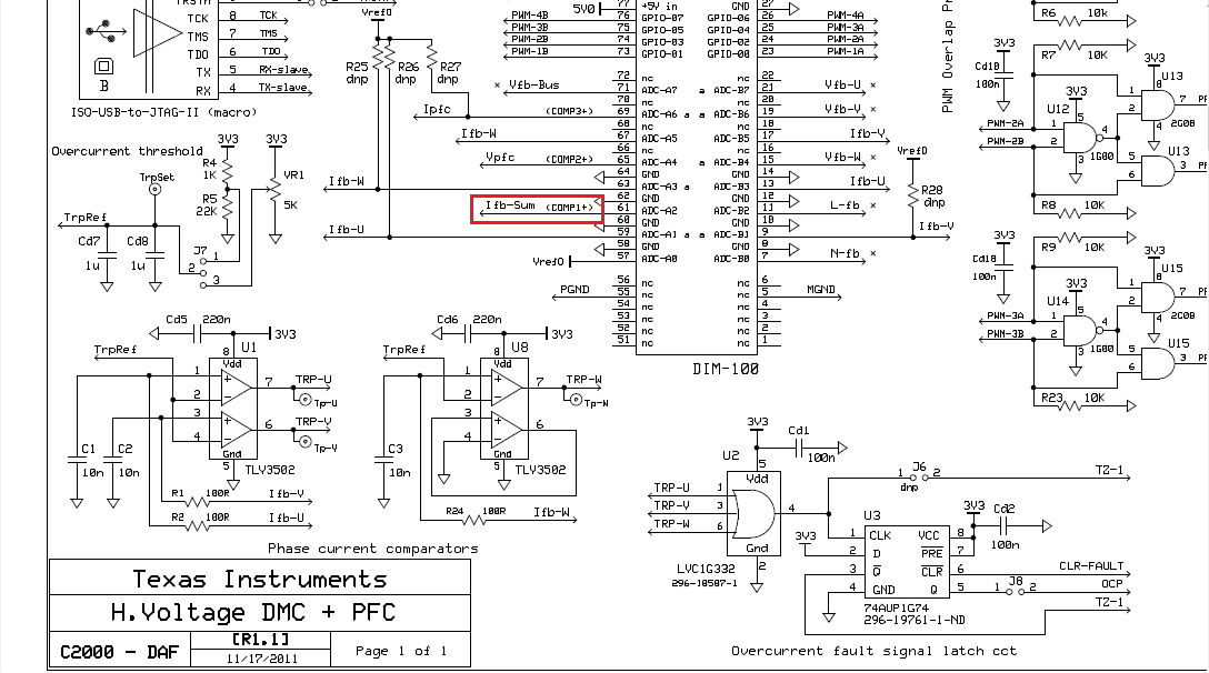
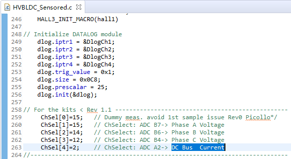
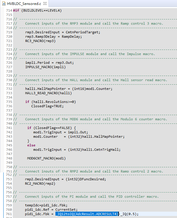
As the pictrue shows above, Ifb-SUM is the sum of feedback current IA, IB, IC. I looked at the current loop control code in the routine. The current (Ifb-SUM) is the bus current.
Question 1: Should the sum of three-phase currents be zero at any time?
For example, Clarke transform usually requires two-phase current, and three-phase bridge drive current will be equipped with two current acquisition circuits (such as AB two-phase), IC = 0-IA-IB.
If so, why is the sum of three-phase current feedback bus current?
Question 2: Will the waveform of Ifb-SUM be the same as that of Shunt resistance or closed-loop Hall current sensor on bus?

Best regards

  • Dear team:

    And

    1, The current amplification factor of bus current acquisition circuit is 24.76 times, right? (2.7K parallel 29.8K, then divided by 100ohm).

    2, If so, considering that the bus current acquisition circuit also has a 1.65V bias voltage, the bus current should only be positive, right?

    3, If the voltage difference between the operational amplifier and the 3.3V voltage rail is neglected and the bias voltage is subtracted by 1.65V, what is the actual current range corresponding to the 1.65V difference?

    How is the magnification factor of 8.25 times labeled in the figure calculated?

    Is this the case: (2000*22000)/(2000+24000)/ 221 = 8.295625942684766?

    But the result wasn't 8.25.

  • The Ifb_sum is not used for motor control, just for overcurrent protection, and it should be equal to the bus current using a current shunt.

    Your calculation is right for phase current sensing.

  • Dear Yanming:

    Thank you for your help.

    As you said:"The Ifb_sum is not used for motor control, just for overcurrent protection"

    But in the schematic of HVMotorCtrl+PFCKit-R1.1, ADC channel A2 is used to collect Ifb_sum:

    If Ifb_sum is not used in current loop control, where does the feedback current in current loop control come from?

    As you can see from the routine (\controlSUITE\development_kits\HVMotorCtrl+PfcKit_v2.1\HVBLDC_Sensored), the current loop control uses Ifb_sum:

    It can be seen from this that what you said "Ifb_sum is not used for motor control, but for overcurrent protection" should be wrong?

    And 

    If you think my calculation of phase current detection is correct,

    Can we take HVMotorCtrl+PFCKit-R1.1 circuit as an example to explain how to calculate the corresponding relationship between the AD acquisition value of bus current and the actual current value of bus current?

    Best regards

  • Sorry, I mean the sensored or sensorless FOC. It's used for trapezoidal BLDC control, you may refer to DRV8312 kit that should be good for a trapezoidal BLDC control if you want to use it.