This thread has been locked.

If you have a related question, please click the "Ask a related question" button in the top right corner. The newly created question will be automatically linked to this question.

CCS/TMS320F28377D: Setting PI parameters

Part Number: TMS320F28377D
Other Parts Discussed in Thread: C2000WARE,

Tool/software: Code Composer Studio

Hello,

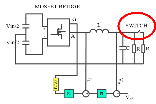
I have simulated half bridge single phase inverter  dual loop outer is voltage loop and inner is current loop with 50Khz switching frequency low power with Vin = 50V and Vo is 15V , Rload is 10ohm and neutral point is connected in between two DC link capacitors(VDC_link= Vin/2 compensator formulla in my simulation is P(1=ITs.1/z-1) and forward Euler integrator method. my simulation working fine, output voltage and current are right. I set KP and KI according to Hit and error method(for current loop Kp=0.05 and KI=6000 upper and lower  limits  are 15 and -15 respectively and for voltage loop KP= 5 and KI =500, upper and lower limits are 3 and -3 repectively ) . After that i have made hardware circuit according to my simulation. i used TMS320F2837xD Dual-Core Delfino™ Microcontrollers, I have written c code in code composer studio V8.2. and i have used Solar library provided by TI in which i used PID_GRANDO. I set derivative term zero and i put same KP and KI paramaters of my simulation in current and voltage loop but it does not work output of both PI contoller are same as their  limits and fixed. could you tell me why is that or i can not used solar lib?  do i need other library ? could you please send me some document or any software which can tune PI parameters for single phase inverters. thanks

  • In principle, you should be able to use the solar library for development, but it is quite old and has not been updated for some time.  Newly developed foundational software is deployed in C2000Ware.  Application specific software is deployed in separate Software Development Kits (SDKs).  There is a Digital Power SDK here:

    http://www.ti.com/tool/C2000WARE-DIGITALPOWER-SDK

    There is a library of control algorithms, including several PI controllers, in C2000Ware.  If you install in the default location you will find them at:

    C:\ti\c2000\C2000Ware_2_00_00_03\libraries\control\DCL 

    I am not familiar with the "hit and error" method you have used.  There is a PID tuning guide in the DCL \docs which outlines a procedure for transient response tuning.  Alternatively, a PI controller is basically an integrator with configurable zero, and there are functions in the DCL to load the controller from a "zero-pole-gain" description.  These are just alternative approaches to the one you have taken thus far.

    I cannot say from the information in your post why your controllers are saturating.  The integral gains seem rather high; so you may like to experiment with lowering those gains to see if it makes a difference.  I wonder also if you have accounted for ADC and PWM gains in your simulation, sine both will contribute to loop gain?

    Regards,

    Richard

  • ok thank you very much i will use DCL library and one more question I am using TMS320F28377D and in my power board i dont have hardware pin of over current protection which i will connect for GPIO for trip zone protection, could you please tell  me how can i do software protection if there is high current or voltage it will trip PWM to Low . and how to define level for over current or voltage. Is there any example code for software over current protection. thanks

  • Software protection is generally not done.  The latency of sampling, triggering and responding to an interrupt is likely to be too high to protect your system if something goes wrong.  The right solution is through hardware using the trip zone feature of the PWM module, as you mentioned.

    If that's not possible, you could make use of the PPB feature in the ADC block.  That has a digital comparator which can detect over/under conditions and generate an event.  You can then route the event to the PWM trip zones via the ePWM X-bar and DC module.  That will be quicker than doing it all in software, but you'll still have the ADC sampling latency.  It won't protect you in a typical fault situation.

    Regards,

    Richard

  • thank you very much i understand and i will make hardware circuit for over current protection. i have one more question as i have mentioned that i have designed single phase half bridge inverter. I am attaching figure in which I have two loads one load is connected through switch  to connect or disconnect load only one time. let suppose first switch is open and one load is connected then after 1 minute I connected another load by turning on switch. this is I called positive step change of load current because when I will connect another load load current will increase same way for negative step change when load is disconnected through switch. and this switch turn on happens at any angle from

    1- 360(0-pi) I want to detect this instant step change through ADC. At evey cycle ADC will sample the load current if the load current is greater than predefined thresholds it means step change  has happened and suddenly detect this particular instant, there  two thresholds upper and lower thresholds. as the formula for step size= full scare range/4096 = 0.7ms . thresholds are selected twice the step size it means upper and lower threshold are 0.7*2=1.4ms  and -1.4ms. so ADC will monitor load current every cycle if its greater than or lower than these thresholds it will detect this step change this is for AC system. for DC system its easy to detect step change thank you very much.   

  • I don't see a question in your post. Also, you seem to be expressing step size in units of time: "step size= full scare range/4096 = 0.7ms"

    Please can you clarify what you are asking?

    Regards,

    Richard

  • my question is how can i use  ADC to detect AC positive or negative load current  step change ? whenever switch is turned ON or OFF how ADC will generate event that particular angel ? and that step change can be at any angel from 0 to 360 ? thanks

  • See

    http://www.ti.com/lit/ug/tiduay6d/tiduay6d.pdf

    typically if you change the load, this will introduce a small instantanoeus voltage error and this will then be corrected by the voltage compensator. 

    See image 3.2.1.3 in the UG above which follows a cascaded control structure for VSI, 

  • yes i was that figure. i want to detect that theta angel where there is step change of load Detect this step change automatically and check if its step up or step down? this step change can be at any point 

  • Shan,

    When you say Automatically excatly what do you mean? happen in hardware, software ? 

    I feel you will need to monitor the voltage error of the current feedback and see if it is deviating too much from the setpoint.

    The question is what is the frequency at which you want to monitor this? 

    GIven the theta angle is computed in the ISR, that will be a good point to monitor and lock the angle in a software variable.

    -Manish  

  • automatically means if there is step change in hardware and if there is step change in hardware switch then load current will increase or decrease according step change either increase or decrease. yes i want to minitor voltage of current error but voltage of current error is sine wave its changing from 0 to Pi and there is always two thresholds upper and lower thresholds on sine error voltage if the voltage go above or lower than these thresholds it can detect that angel et suppose step change can be at 30 degree or 60 degree or any angel between 0 to 360. so when there is step change in hardware then how can i detect step change theta in software.

  • Shah, 

    We are not supposed to write code for you, the below is the max I am able to support which is outside the scope already of what we can offer as we do not provide engineering consultancy. 

    For example in the code i pointed to you above, we are generating the angle using a ramp

    //
    // Generate the RAMP angle
    RAMPGEN_run(&rgen1);
    //
    // Use the angle value to compute the sine value
    invSine = sin((rgen1.out)*6.283185307);

    Then this is used to generate a AC waveform,

      invVoRefInst = invSine * invVoRef;

    You can monitor the error

    voltage_error= invVoRefInst - invVoInst;

    by taking an absolute of the above and storing the rgen1.out in a desired variable.