This thread has been locked.

If you have a related question, please click the "Ask a related question" button in the top right corner. The newly created question will be automatically linked to this question.

TMS320F28379S: EnDat library problem

Part Number: TMS320F28379S


Hello

After make working the Biss library without any problem, I'm facing problem with the EnDat.

From the exemple code, the data receive during the delay compensation are bad due to the CRC check.

I comment the "ESTOP0" instruction to continue.

Then I receive Data position, but CRC is bad also always.

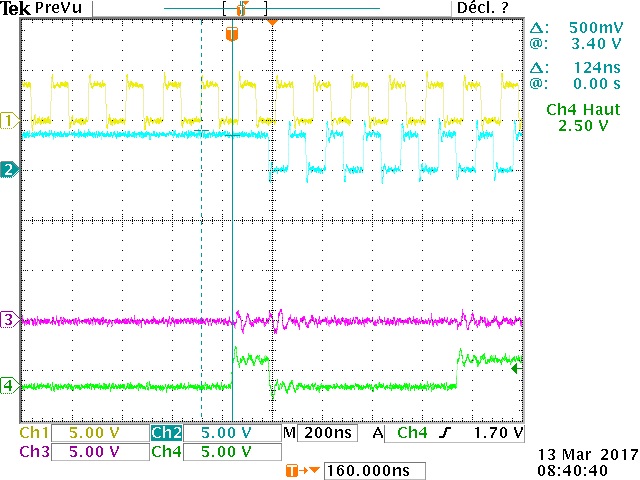
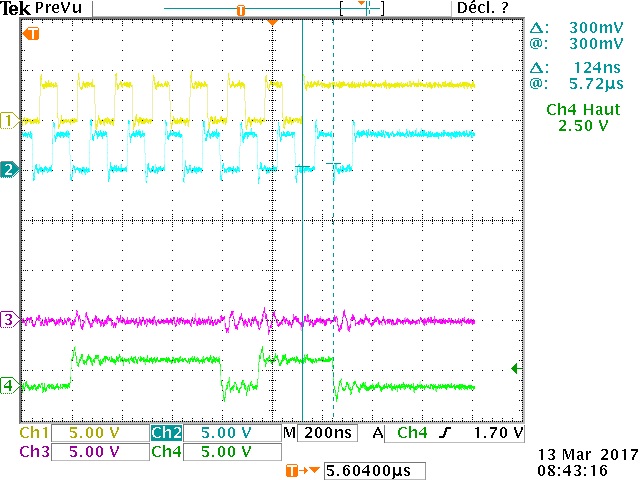
Then, I read the SPI signal.

CH1 Yellow: GPIO 6 EnDat Sensor Clock

CH2: Blue: GPIO 7 SPI Slave Clock

CH3: GPIO 34 ENDAT_DIR

CH4: Green: SPISIMO = ENDAT_DIN

I read the SPI config register, POLARITY = 1, and CLKPHASE = 0. Then this means "Falling edge without delay" So input data are sampled on SPI Clk rising edge, when  EnDatSensor update data on th rising edge of its clock.

But according the scope, the rising edge of SPI is near to the rising edge of the Sensor.. I think SPI input some time bad sample because Rising edge come to fast?

Receive SPI Data for the scope above is : 0x0031, 0x872C, 0xA497. Some word are Ok, but some are bad where on SPI Data, I thing read: 0x0031 A69C 1D24

Calculated compensation delay (even if CRC bad) is 13.

SPI clock always let to 200KHz (not change to 8MHz... but same problem at 8MHz)

sensor is Heidenhain EQI1331

Thank

  • Hi,

    Great to hear that you've the BiSS-C interface working. Thanks for the detailed diagrams.

    I'm wondering why the received CRC is always a fixed number - is the encoder response a valid response or an error response?
    Also,

    A GIR said:
    I read the SPI config register, POLARITY = 1, and CLKPHASE = 0. Then this means "Falling edge without delay" So input data are sampled on SPI Clk rising edge, when  EnDatSensor update data on th rising edge of its clock.

    As you would have noted the SPI CLK and the encoder clock will be operating in different phases to capture the data correctly (for delay compensation).
    For some reason the phase alignment doesn't seem to be correct from the wave forms. 
    Could manually change the POLARITY and CLKPHASE values see if the data value is captured properly?
    You could also try to change the delay_comp value, but that doesn't seem to be the problem as you are seeing fail at low frequency, even without delay compensation.

    Are you using a long cable in your test?


  • Hello,

    I'm using a 2m câble.

    I try with a clock of 8.33MHZ (ENDAT_RUNTIME_FREQ_DIVIDER= 6), the phase seems better. This means at low frequency, tere are a problem in computation of the phase delay?

    But with ENDAT_RUNTIME_FREQ_DIVIDER = 6, the last clock pulse is shorter!... this is strange..

    So I set ENDAT_RUNTIME_FREQ_DIVIDER to 7. (= 7.14MHz)

    Clock phase seems Ok.

    The measure delay by the library is 13 (= 130ns?). If I understood, this delay is measure between the Rising Edge of the clock and the Bit Start rising edge. With the scope, I measured 124ns. (Screenshot)

    Note this delay correspond aproximately to my Frequency (T = 140ns). THis is why the scope could be confused because we must keep in mind the 130ns delay between the Endat Clock and the received data.

    This is why into the screenshot, we can see a pulse of the SPI clock about 1 period later than the last pulse of the clock Endat.

    I try to set the delay_compens to 0 instead of 13 (before call PM_endat22_setFreq because it seem the delay_compens is only taken with the call of PM_endat22_setFreq function. I'm right?) but 0 instead of 13 provide exacltly the same graph... Why??...

    So If I undestand, the SPI clock start after the detection of the MOSI is set (Start bit) to receive position data. The Start bit is following by e1 en e2 bit.

    Sometime these bits are 0. But many time one or both or either are to 1!... (but in software, never variable error1 or error2 are set..)

    Then the following graph are taken when both are to 0..

    From the SPI point of view, I get the following sequence bit (48bits = 3x 16bits):

    0000 0000 0000 0011 1110 0111 0010 0100 1010 0100 1111 0110

    this correspond to the Hexa code 03 E724 A4F6. This is exaclty that I received into the SPI buffer: rdata = [0x0003, 0xE724, 0xA4F6]

    Then this sequence correspond to these format:

    0000 0000 0 ; 00 - 000 1111 1001 1100 1001 0010 1001 0011 -1 1011 -0 (Tx way ; e1 e2 - Position 31 bits - CRC - Last (high or low according tm)

    Like bit are in the reverse order (MSB/LSB) the revert sequence give following:

    0- 1 1011 - 110 0100 1010 0100 1001 1100 1111 1000 - 00 ;0 0000 0000 (X - CRC - Pos 31 bits - e2 e1; tx way)

    this provide Hex code : 0x1B - 0x64A4 9CF8

    But after call of PM_endat22_receiveData:

    - the position_lo get 0x49 49 39 F0

    - data= 0

    - data_crc = 0x001D

    -After call PM_endat22_getCrcPos, crc5_result = 0x000B

    If we read the above sequence and we shift it to the left of 1 bit, we get:

    01 - 10111 - 100 1001 0100 1001 0011 1001 1111 0000 - 00;  0000 0000 (XX - CRC - Pos 31 bits - e2 e1; tx way)

    => position hex code give : 0x49 49 39 F0 ==== equal position_lo

    Total frame:

    I

    Zoom on the start bit and the delay (124ns)

    Zoom on the last Endat clock, where the line should be set to 1 after the propagation delay time..  but pass to 0!...

    Then I don't know how make work properly. I'm lose to know how resolve the problem?...where is my problem?

    According the set frequency some clock seem different, phase/delay, get result.. this is not easy to understand better how know the behavior/ the code of the EnDat library...

    How TI can help me?:

    When e1, e2 bit are are 0 CRC computation is bad, many time, one of e1/e0 is set..??

    But: all time, I compute the "motor position" with Multiturn/monoturn hexa code get by the library: It is always cohrent. When rotor execute 1 lap, position change by 1 lap...

    Note: into exemple: spiRxFifoIsr: the loop is done from i = 0 to i<= FIFO_size

    I Think we should write from i = 0 to i< FIFO_size

  • Hello

    I have some news.

    In fact I f I call the function endat22_setupAddlData then in the main loop I call the function endat22_readPositionWithAddlData, this working. Except the error 2 always set.

    But If i call endat21_readPosition function to get only position without Additional data: CRC fail...

    I change this function when call the PM_endat22_getCrcPos change the parameter ENDAT21 to ENDAT22 but without success.

    Is possible to use simple GetPosition instruction into endat2.2? I think yes!??

    Other try, into endat22_setupAddlData; when call PM_endat22_setupCommand and PM_endat22_receiveData, I change last parameter set to 2 by 0 (Add data)

    But CRC is bad half time. And the scope is very strange, 1 transmission is Ok, then CLock pulse are keep during 15ms.. then new tranmssion start..

    How use the Endat2.1 instruction to get only the position with EnDat2.2. Must change anything into endat22_setupAddlData to disable additional Data?

  • Hi,

    A GIR said:
    In fact I f I call the function endat22_setupAddlData then in the main loop I call the function endat22_readPositionWithAddlData, this working. Except the error 2 always set.


    Is this some property of the encoder? I'm wondering if the ENDAT21 command which doesn't use additional data is causing a different behavior.
    As I understand, if the encoder supports ENDAT22 commands, the ENDAT21 commands should be a subset of the supported commands and should work as expected. I'm not aware of any special handling needed for EnDat21 command.
    In fact, removing additional data would be same as endat21_readPosition. I've en ENDAT22 encoder ROC25 and tested both commands, with and without additional data, and works fine.
    Regarding error2 - please check the encoder protocol specification for the expected value. I believe, some encoders send out error1=0, and error2=1 by default.
    If the CRC is matching then i would expect that the received value is correct.

    From your previous post -
    I wondered if there is any glitch on the line which is corrupting the data capture and potentially even resulting in miscalculation of the delay compensation.
    But, now that you say that the endat22_setupAddlData is working then the timing is exactly the same for all interface commands. There is no reason why some commands should work and some do not.
    In case, from your waveforms, you feel that SPI clock is coming earlier than expected - I suggest, for the test purposes, you enable the GPIO synchronizer for the SPI clock input in alone. This should add couple of cycles of delay w.r.t. the data input.