Hi,
we are using a F28075 device Sys Clock running at 100 MHZ, ePWM running at 100 MHz to generate a 16 KHz period sinusoidal waveform using ePWM6 (carrier 450 KHz) to control a bulb filament current
- ePWM6 generates an INT every time cntr = 0 and a SOC signal to convert the current (i_fil) at 2x 16 KHz and to launch the PI control for i_fil (CLA Task4)
- CLA Task3 updates ePWM6 CMPA with CLA RAM sine table: 450 KHz (every ePWM6 INT). This task takes 300 nS to get done (<<< 2.222 uS period)
- CLA Task4 modulates sine waveform, 16 KHz (every i_fil EOC). This task gets 1000 nS to get done (<<< 62.5 uS period)
- ePWM6 Period and CPMA are configured in Shadow Mode
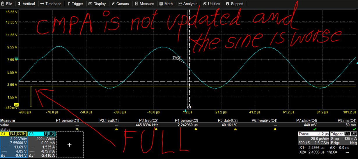
We get a ePWM6 signal period varying between 2.22 and 2.62 uS (jitter) when CLA task is copying the corresponding sine table value from CLA RAM to CMPA reg, but it should be constant. The only thing that should be changing is the signal duty cycle. The consecuence is a wrong sine wave. The debugger shows that sometimes SHDWAFULL bit is 1 when updating CMPA at CLA Task3
Tests:
- if CLA Task 4 is NOT modifying CMPA reg. (Init CMPA=HALF_PERIOD) --- > period = 2.22 uS (450 KHz) perfectly constant, no jitter,
- if we copy HALF_PERIOD - sine_index (0-27) instead of sine table value into CMPA we get period jitter also and a triangular wave
- Disabling High Res PWM
- Disabling all clk ePWM modules int the app but ePWM6 one
- Decreasing CLA Task rate to 150 KHz. The jitter decrease, but still present
- Changing into “inmediate” instead of “shadow” mode for ePWM6
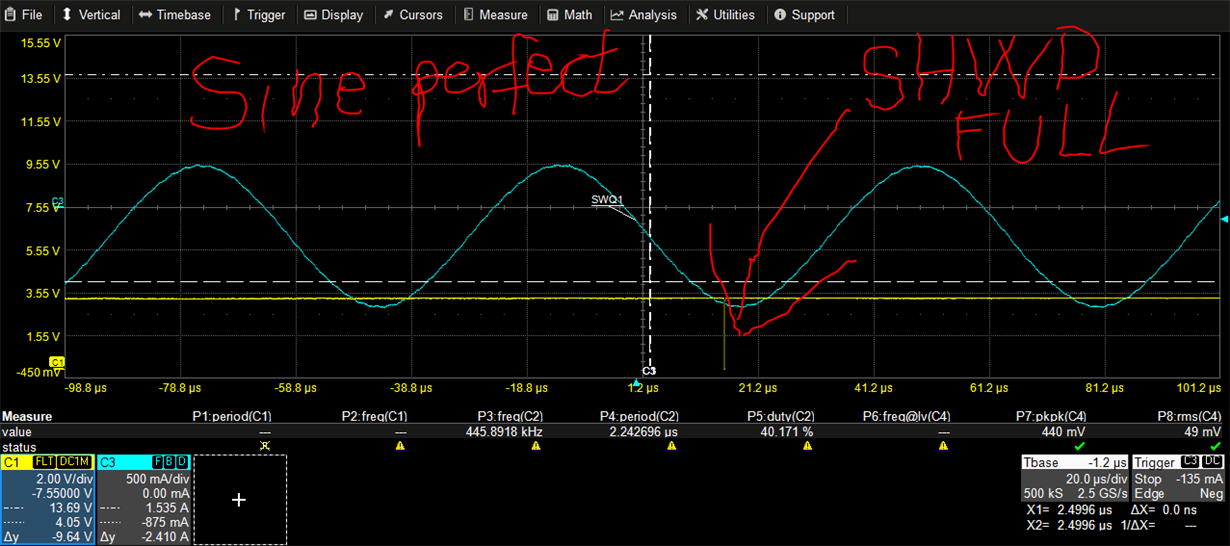
- if SHDWAFULL bit is 1 we set a GPIO output to Low for a several nops time to show the situation in the scope. The sine wave seems to be OK when that bit is 1, but sometimes is wrong when the bit is zero.
- if SHDWAFULL bit is 1 we don’t update CMPA. The sine is even worse
None of the above tests fix the jitter problem
QUESTION: Can CMPA be written at a high rate like ePWM period?
Project code is attached (FilControl.zip)
the ePWM config and CLA tasks code is below
Figure 1. the sine wave is not correct in the red arrow area (it is corresponding with a wrong PWM period) but bit SHWDFULL (yello signal, C1, active low) is not active
Figure 2. Shows that bit SHWDFULL (yello signal, C1, active low) is 1, but the sine wave is perfect

 Figure 3. Shows that is we don’t update CMPA when SHDWA bit is active the sine wave gets even worse than updating it (comparing with figure 2)
// 16 KHz Sinusoidal generation using ePWM6, carrier 450 KHz (CLA Task 3 updates CMPA with sine table), CLA Task 4 modulates sine (16 KHz)
// F28075 Sys Clock running at 100 MHZ, ePWM running at 100 MHz
#define SYSCLK (float)100E6 // = 10MHz x 10 // El cast es necesario para luego poder multiplicarlo
#define SYSCLK_MHZ (Uint32)100 // = 10MHz x 10
#define FIL_SW_FREQ 450E3 // Hz
#define FIL_PWM_PERIOD (int)(SYSCLK_MHZ*1E3/(2*(FIL_SW_FREQ/1E3)))
#define PLL_CLOCK_SOURCE INT_OSC1 // 10 MHz
#define PLL_INTEGER_MULT IMULT_10 // x10
#define PLL_FRACTIONAL_MULT FMULT_0
#define PLL_DIVISOR PLLCLK_BY_1 // x1/1
#define FIL_FREQ_MOD 16E3 // Hz
#define CARRIER_MOD_RATIO (Uint16)(FIL_FREQ_CARRIER/FIL_FREQ_MOD) // carrier 28 ticks per mod. cicle
#define TICKS_SENOIDAL_PERIOD (unsigned int)(CARRIER_MOD_RATIO-1)
// Sys clock init
InitSysPll(PLL_CLOCK_SOURCE,PLL_INTEGER_MULT,PLL_FRACTIONAL_MULT,PLL_DIVISOR);
asm(" EALLOW"); // Enable EALLOW protected register access
ClkCfgRegs.PERCLKDIVSEL.bit.EPWMCLKDIV = 0; // EPWMCLK = SYSCLK
CpuSysRegs.PCLKCR0.bit.TBCLKSYNC = 0;
asm(" EDIS");
...
InitEPWM();
...
/* Enable the clocks to the ePWM module. */
asm(" EALLOW");
CpuSysRegs.PCLKCR0.bit.TBCLKSYNC = 1; // TBCLK to ePWM modules enabled
asm(" EDIS");
void InitEPWM_Fil(void)
{
asm(" EALLOW");
CpuSysRegs.PCLKCR2.bit.EPWM6 = 1; // SYSCLKOUT to ePWM6 enabled
CpuSysRegs.PCLKCR0.bit.HRPWM = 1; // SYSCLKOUT to HRPWM enabled
// El seno del filamento es una onda simétrica. Usar el modo up-down count
EPwm6Regs.TBCTL.all = 0; // default values
EPwm6Regs.TBCTL.bit.CTRMODE = 2; // up-down count mode (para ondas simétricas como la senoidal)
EPwm6Regs.CMPCTL.all = 0; // CMPA/B in shadow mode. Load CMPA/B when CTR=Zero
EPwm6Regs.TBCTL.bit.CLKDIV = 0; //
EPwm6Regs.TBCTL.bit.HSPCLKDIV = 0; //
EPwm6Regs.TBCTL.bit.FREE_SOFT = 2; // free run in emulation
EPwm6Regs.TBCTL.bit.PRDLD =0;// load the PERIDOD register from the shadow register when the time base register is cero
EPwm6Regs.TBPRD = (unsigned int)FIL_PWM_PERIOD;// 450 kHz PWM frequency con un SYSCLK de 100MHz
EPwm6Regs.CMPCTL.all = 0; // CMPA/B in shadow mode. Load CMPA/B when CTR=Zero
EPwm6Regs.CMPA.bit.CMPA =0; // initial duty 0 % // para evitar pico de corriente
EPwm6Regs.CMPA.bit.CMPAHR = 0; // Set HRPWM
EPwm6Regs.CMPB.bit.CMPBHR = 0; // Set HRPWM
// En modo up-down count y modulación unipolar (ePWM_B output)
EPwm6Regs.AQCTLB.all = 0;
EPwm6Regs.AQCTLB.bit.CAU = AQ_CLEAR;
EPwm6Regs.AQCTLB.bit.CAD = AQ_SET;
EPwm6Regs.HRCNFG.all = 0x0;
EPwm6Regs.HRCNFG.bit.EDGMODE = HR_FEP; // MEP control on falling edge
EPwm6Regs.HRCNFG.bit.EDGMODEB = HR_FEP;
EPwm6Regs.HRCNFG.bit.CTLMODE = HR_CMP;
EPwm6Regs.HRCNFG.bit.CTLMODEB = HR_CMP;
EPwm6Regs.HRCNFG.bit.HRLOAD = HR_CTR_ZERO;
EPwm6Regs.HRCNFG.bit.HRLOADB = HR_CTR_ZERO;
// Habilitar esta INT para hacer la senoidal y control del fil en la CLA
EPwm6Regs.CMPA.bit.CMPA =(unsigned int)(FIL_PWM_PERIOD >> 1);
EPwm6Regs.ETSEL.bit.INTEN = 1; // Enable ePWM_INT
EPwm6Regs.ETSEL.bit.INTSEL = 1; // Start INT when CTR = ZERO
EPwm6Regs.ETPS.bit.INTPRD = 1;// generate EPwm_INT on each event on ETPS[INTCNT]
// Configure ePWM6 to generate SOCA event using the prescaler
EPwm6Regs.ETSEL.bit.SOCAEN = 1; // Enable EPwm SOCA (manage by sine CLATask to sync)
EPwm6Regs.ETSEL.bit.SOCASEL = 2; // start SOCA when CTR = PRD
EPwm6Regs.ETPS.bit.SOCPSSEL = 1; // select SOCAPRD2]
EPwm6Regs.ETSOCPS.bit.SOCAPRD2 = 14; // generate SOCA on divisor event on ETPS[SOCACNT]
//Really use the OST to enable/disable. AQSFRC is not used
EPwm6Regs.AQSFRC.bit.ACTSFA = 1; // EPwm will be 0 when one_time software force A is invoked
EPwm6Regs.AQSFRC.bit.ACTSFB = 1; // EPwm will be 0 when one_time software force B is invoked
EPwm6Regs.AQCSFRC.bit.CSFB = 1; // forcing enabled (Realmente sale por el B)
}
//////////////////////////////////////////////////////////////////////////////////////////////
//ADC Config to convert filament current and launch CLA Task4 at the EOC
AdcbRegs.ADCINTSOCSEL1.bit.SOC0 = 0; // No ADCINT will trigger SOC0. TRIGSEL field determines SOC0 trigger
AdcbRegs.ADCSOC0CTL.bit.TRIGSEL = ADC_TRIGGER_SOURCE_ePWM6_SOCA;
AdcbRegs.ADCSOC0CTL.bit.CHSEL = 2; // Convert channel ADC B2
// For S/H RC Rs=1K Ch=16.5 pF (modelo de MEAS_FIL_I y el Ch del sample and hold) obtenemos el min ACQPS = 19 (160 nS)
AdcbRegs.ADCSOC0CTL.bit.ACQPS = 20;
AN_SMALL_FILAMENT_CURRENT = &AdcbResultRegs.ADCRESULT0;
// Configuration for EOC (SOC0) to trigger ADCINT (to start Cla Task4)
AdcbRegs.ADCINTSEL1N2.bit.INT1SEL = 0; // (Sel SOC0 to trigger ADCINT1)
AdcbRegs.ADCINTSEL1N2.bit.INT1E = 1; // Enable ADCINT1
AdcbRegs.ADCCTL1.bit.INTPULSEPOS = 1;// INT is triggered when conv result is latch into ADCresultRegister
AdcbRegs.ADCINTSEL1N2.bit.INT1CONT = 1; // No further ADCINT1 pulses are generated until ADCINT1 flag is cleared by user.
AdcbRegs.ADCINTFLGCLR.bit.ADCINT1 = 1; // Clear ADCINT1 flag
AdcbRegs.ADCSOCPRICTL.bit.SOCPRIORITY = 0x04; // SOC0-SOC3 are high priority, SOC4-SOC15 are in round robin
//////////////////////////////////////////////////////////////////////////////////////////////
#pragma DATA_SECTION(m_fil_sin, "CLADataLS");
float m_fil_sin[CARRIER_MOD_RATIO];
interrupt void Cla1Task3 ( void ) // 450 KHz (every ePWM6 INT)
{
EPwm6Regs.ETCLR.bit.INT = 1; //clear interrupt flag
if( m_SineIndex > TICKS_SENOIDAL_PERIOD) {
m_SineIndex = 0;
}
faux_sine = m_Mod * m_fil_sin[__mf32toui16r(m_SineIndex)];
faux1_sine = HALF_FIL_PWM_PERIOD + faux_sine;
aux_CMPA = ((Uint32)faux1_sine) << 16; //calculate CMPA and prepare to write in ePWM
faux3_sine = __mfracf32(faux1_sine) * 64; //extract fractional part for HRPM
EPwm6Regs.CMPA.all = aux_CMPA + ( ((Uint32)faux3_sine ) << 8);
m_SineIndex++;
}
///////////////////////////////////////////////////////////////////////////////////////////////
interrupt void Cla1Task4 ( void )
{
float error_I_sf;
float out_sf_presat;
AdcbRegs.ADCINTFLGCLR.bit.ADCINT1 = 1; // Clear ADCINT1 flag
if(m_Task4TriggerTick) // 16 KHz
{
m_Task4TriggerTick = 0;
Fdbk_I_sf = AdcbResultRegs.ADCRESULT0; // Lee la corriente que circula por el fil ADCINB2 (SOC0)
error_I_sf = Ext_Ref_I_sf - Fdbk_I_sf;
Acc_I_sf += ki_I_sf * error_I_sf + kaw_I_sf * sat_error_I_sf;
out_sf_presat = kp_I_sf * error_I_sf + Acc_I_sf;
out_sf_presat /= ADC_FULL_SCALE; // 1/4095 FS normalize
m_Mod = __mminf32(out_sf_presat, max_out_sf);
m_Mod = __mmaxf32(m_Mod, min_out_sf);
sat_error_I_sf = m_Mod - out_sf_presat;
}
m_Task4TriggerTick++;
}


