Part Number: TMS320F28021
Other Parts Discussed in Thread: SN65HVD1781, C2000WARE
Hi all,
I have a basic a setup of a master-slave system, where the master is sending a predefined message to the slave and the slave echo backs this message. Both master and slave the same microprocessor TMS320F28021DAS of the family TMS320F2802x, and they are communicating to each other through RS-485 transceiver SN65HVD1781.
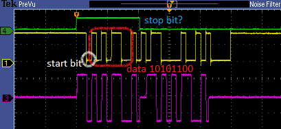
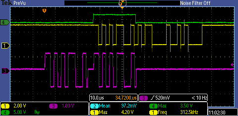
I have a doubt concerning the signal generated by the microprocessor and sent to the transceiver. As shown below, the green trace shows the enable signal (of master) during the data transmission in yellow (8 bit message predefined to 00110101b). This yellow trace is going through the transceiver input, and pink trace corresponds on the transceiver output in differential. After a short rest period, we can see the slave sending back the message.
MASTER TRANMSSION
SLAVE TRANSMISSION
My question is: if I have configured my code to send an 8 bit character with 1 stop bit, why does the sent signal by TMS320F2802x (yellow) look like that? It seems to send two times the messages and after it has some random values. Where is the stop bit? Is my peripheral configuration correct?
FYI, the master and slave understand each other, in debug mode RXTX fifo registers have the correct value (00110101b).
Any help is welcomed. Thanks in advance.
here is my code :
You can find the master configuration code I did just below:
//
// Included Files
//
#include "DSP28x_Project.h" // Device Headerfile and Examples Include File
#include "stdio.h"
#include "stdlib.h"
#include "time.h"
#include "common/include/adc.h"
#include "common/include/clk.h"
#include "common/include/flash.h"
#include "common/include/gpio.h"
#include "common/include/pie.h"
#include "common/include/pll.h"
#include "common/include/sci.h"
#include "common/include/wdog.h"
//
// Functions Prototypes
//
bool SCI_VD_isTxEmpty();
void scia_echoback_init(void);
void scia_fifo_init(void);
void scia_xmit(int a);
void scia_msg(char *msg);
//
// Globals
//
ADC_Handle myAdc;
CLK_Handle myClk;
FLASH_Handle myFlash;
GPIO_Handle myGpio;
PIE_Handle myPie;
SCI_Handle mySci;
//
// Main
//
void main(void)
{
uint32_t LoopCount;
uint16_t sentChar;
uint16_t ReceivedChar;
char *msg;
uint16_t delay1;
uint16_t delay2;
CPU_Handle myCpu;
PLL_Handle myPll;
WDOG_Handle myWDog;
//
// Initialize all the handles needed for this application
//
myAdc = ADC_init((void *)ADC_BASE_ADDR, sizeof(ADC_Obj));
myClk = CLK_init((void *)CLK_BASE_ADDR, sizeof(CLK_Obj));
myCpu = CPU_init((void *)NULL, sizeof(CPU_Obj));
myFlash = FLASH_init((void *)FLASH_BASE_ADDR, sizeof(FLASH_Obj));
myGpio = GPIO_init((void *)GPIO_BASE_ADDR, sizeof(GPIO_Obj));
myPie = PIE_init((void *)PIE_BASE_ADDR, sizeof(PIE_Obj));
myPll = PLL_init((void *)PLL_BASE_ADDR, sizeof(PLL_Obj));
mySci = SCI_init((void *)SCIA_BASE_ADDR, sizeof(SCI_Obj));
myWDog = WDOG_init((void *)WDOG_BASE_ADDR, sizeof(WDOG_Obj));
//
// Perform basic system initialization
//
WDOG_disable(myWDog);
CLK_enableAdcClock(myClk);
(*Device_cal)();
//
// Select the internal oscillator 1 as the clock source
//
CLK_setOscSrc(myClk, CLK_OscSrc_Internal);
//
// Setup the PLL for x10 /2 which will yield 50Mhz = 10Mhz * 10 / 2
//
PLL_setup(myPll, PLL_Multiplier_8, PLL_DivideSelect_ClkIn_by_2);
//
// Disable the PIE and all interrupts
//
PIE_disable(myPie);
PIE_disableAllInts(myPie);
CPU_disableGlobalInts(myCpu);
CPU_clearIntFlags(myCpu);
//
// If running from flash copy RAM only functions to RAM
//
#ifdef _FLASH
memcpy(&RamfuncsRunStart, &RamfuncsLoadStart, (size_t)&RamfuncsLoadSize);
#endif
//
// Initialize GPIO
//
GPIO_setPullUp(myGpio, GPIO_Number_6, GPIO_PullUp_Enable);
GPIO_setPullUp(myGpio, GPIO_Number_28, GPIO_PullUp_Enable);
GPIO_setPullUp(myGpio, GPIO_Number_29, GPIO_PullUp_Disable);
GPIO_setQualification(myGpio, GPIO_Number_28, GPIO_Qual_ASync);
GPIO_setMode(myGpio, GPIO_Number_6, GPIO_6_Mode_GeneralPurpose);
GPIO_setMode(myGpio, GPIO_Number_28, GPIO_28_Mode_SCIRXDA);
GPIO_setMode(myGpio, GPIO_Number_29, GPIO_29_Mode_SCITXDA);
GPIO_setDirection(myGpio, GPIO_Number_6, GPIO_Direction_Output);
//
// Setup a debug vector table and enable the PIE
//
PIE_setDebugIntVectorTable(myPie);
PIE_enable(myPie);
LoopCount = 0;
sentChar = 0x0035;
scia_echoback_init(); // Initialize SCI for echoback
scia_fifo_init(); // Initialize the SCI FIFO
msg = "\r\n";
for(LoopCount=0;LoopCount<10000;LoopCount++)
{
GPIO_setHigh(myGpio, GPIO_Number_6);
scia_xmit(sentChar);
scia_msg(msg);
//while(SCI_VD_isTxEmpty()){}
GPIO_setLow(myGpio, GPIO_Number_6);
//
// Wait to completely have sent the msg
//
while(SCI_VD_isTxEmpty()){}
//
// After sending the msg, Reset the Rx Fifo to wait the echoback
// This must be done several CPU cycles receiving the message so
// there are no problem with the Rx buffer
//
SCI_resetRxFifo(mySci);
//
// Wait for echoback from the slave
//
while(SCI_getRxFifoStatus(mySci) < SCI_FifoStatus_1_Word)
{
}
//
// Get character
//
ReceivedChar = SCI_getData(mySci);
for(delay1=0; delay1<=5; delay1++)
{
for(delay2=0; delay2<=5; delay2++)
{}
}
//SCI_resetTxFifo(mySci); // No needed
}
}
//
// scia_echoback_init - Test 1, SCIA DLB, 8-bit word, baud rate 0x000F,
// default, 1 STOP bit, no parity
//
void
scia_echoback_init()
{
CLK_enableSciaClock(myClk);
//
// 1 stop bit, No loopback, No parity,8 char bits, async mode,
// idle-line protocol
//
{
SCI_disableParity(mySci);
SCI_setNumStopBits(mySci, SCI_NumStopBits_One);
SCI_setCharLength(mySci, SCI_CharLength_8_Bits);
SCI_setMode(mySci, SCI_Mode_IdleLine);
SCI_enableTx(mySci);
SCI_enableRx(mySci);
//SCI_enableTxInt(mySci);
//SCI_enableRxInt(mySci);
//SCI BRR = LSPCLK/(SCI BAUDx8) - 1
#if (CPU_FRQ_60MHZ)
SCI_setBaudRate(mySci, (SCI_BaudRate_e)194);
#elif (CPU_FRQ_50MHZ)
SCI_setBaudRate(mySci, (SCI_BaudRate_e)162);
#elif (CPU_FRQ_40MHZ)
SCI_setBaudRate(mySci, (SCI_BaudRate_e)0);
#endif
SCI_enable(mySci);
}
return;
}
//
// scia_xmit - Transmit a character from the SCI
//
void
scia_xmit(int a)
{
while(SCI_getTxFifoStatus(mySci) != SCI_FifoStatus_Empty)
{
}
SCI_putData(mySci, a);
}
//
// scia_msg -
//
void
scia_msg(char * msg)
{
int i;
i = 0;
while(msg[i] != '\0')
{
scia_xmit(msg[i]);
i++;
}
}
//
// scia_fifo_init - Initialize the SCI FIFO
//
void
scia_fifo_init()
{
SCI_enableFifoEnh(mySci);
SCI_resetTxFifo(mySci);
//SCI_clearTxFifoInt(mySci);
SCI_resetChannels(mySci);
//SCI_setTxFifoIntLevel(mySci, SCI_FifoLevel_Empty);
SCI_resetRxFifo(mySci);
//SCI_clearRxFifoInt(mySci);
//SCI_setRxFifoIntLevel(mySci, SCI_FifoLevel_4_Words);
return;
}
bool SCI_VD_isTxEmpty()
{
SCI_Obj *sci = (SCI_Obj *)mySci;
bool_t status;
status = (sci->SCICTL2 & SCI_SCICTL2_TXEMPTY_BITS) >> 6;
return((bool)status);
}
//
// End of File