Tool/software: Code Composer Studio
Hi,
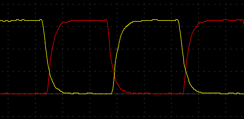
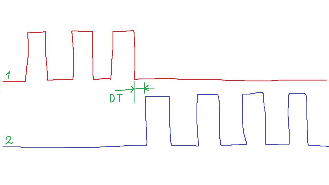
I configured dead time at 18.75ns between PWM1A and PWM1B. Dead time is working. but the problem is that I set the duty of PWM1B to 0, but despite this, it is inverted relative to PWM1A.
I need no inversions.
EALLOW;
    GpioCtrlRegs.GPAPUD.bit.GPIO0 = 1;  // Disable pull-up on GPIO0 (EPWM1A)
    GpioCtrlRegs.GPAMUX1.bit.GPIO0 = 1; // Configure GPIO0 as EPWM1A
    GpioCtrlRegs.GPAPUD.bit.GPIO1 = 1;  // Disable pull-up on GPIO1 (EPWM1B)
    GpioCtrlRegs.GPAMUX1.bit.GPIO1 = 1; // Configure GPIO1 as EPWM1B

    GpioCtrlRegs.GPAPUD.bit.GPIO2 = 1;
    GpioCtrlRegs.GPAMUX1.bit.GPIO2 = 1;
    GpioCtrlRegs.GPAPUD.bit.GPIO3 = 1;
    GpioCtrlRegs.GPAMUX1.bit.GPIO3 = 1;
    EDIS;

    EPwm1Regs.TBCTL.bit.HSPCLKDIV = 0;

    EPwm2Regs.TBCTL.bit.PRDLD = TB_SHADOW; // set Immediate load
    EPwm1Regs.TBPRD = period - 1;          // PWM frequency = 1 / period
    EPwm1Regs.CMPA.bit.CMPA = period / 2;  // set duty 50% initially
    EPwm1Regs.CMPA.bit.CMPAHR = (1 << 8);  // initialize HRPWM extension
    EPwm1Regs.CMPB.bit.CMPB = period / 2;  // set duty 50% initially
    EPwm1Regs.CMPB.all |= (1 << 8);        // initialize HRPWM extension

    EPwm1Regs.TBPHS.all = 0;
    EPwm1Regs.TBCTR = 0;

    EPwm1Regs.TBCTL.bit.CTRMODE = TB_COUNT_UP;
    EPwm1Regs.TBCTL.bit.PHSEN = TB_DISABLE;
    EPwm1Regs.TBCTL.bit.SYNCOSEL = TB_SYNC_IN;
    EPwm1Regs.TBCTL.bit.HSPCLKDIV = TB_DIV1;
    EPwm1Regs.TBCTL.bit.CLKDIV = TB_DIV1;
    EPwm1Regs.TBCTL.bit.FREE_SOFT = 11;

    //dead time
    EPwm1Regs.EPWMXLINK.bit.GLDCTL2LINK = 0;
    EPwm1Regs.DBCTL.bit.OUT_MODE = DB_FULL_ENABLE;
    EPwm1Regs.DBCTL.bit.POLSEL = DB_ACTV_HIC;
    EPwm1Regs.DBCTL.bit.IN_MODE = DBA_ALL;
    EPwm1Regs.DBCTL.bit.SHDWDBREDMODE = 1;
    EPwm1Regs.DBCTL.bit.SHDWDBFEDMODE = 1;
    EPwm1Regs.DBCTL.bit.LOADREDMODE = 0;    // Load on Counter == 0
    EPwm1Regs.DBCTL.bit.LOADFEDMODE = 0;    // Load on Counter == 0
    EPwm1Regs.DBCTL.bit.HALFCYCLE = 1;
    EPwm1Regs.DBRED.bit.DBRED = 4;
    EPwm1Regs.DBREDHR.bit.DBREDHR = (41.75) * 256;//18.75ns
    EPwm1Regs.DBFED.bit.DBFED = 4;
    EPwm1Regs.DBFEDHR.bit.DBFEDHR = (41.75) * 256;

    EPwm1Regs.HRCNFG2.bit.EDGMODEDB = HR_BEP;    // DBREDHR and DBFEDHR
    EPwm1Regs.HRCNFG2.bit.CTLMODEDBRED = 0; // Load on ZRO
    EPwm1Regs.HRCNFG2.bit.CTLMODEDBFED = 0; // Load on ZRO
    EPwm1Regs.DBREDHR.bit.DBREDHR = (0 << 9);
    ////dead time

    EPwm1Regs.CMPCTL.bit.LOADAMODE = CC_CTR_ZERO;
    EPwm1Regs.CMPCTL.bit.LOADBMODE = CC_CTR_ZERO;
    EPwm1Regs.CMPCTL.bit.SHDWAMODE = CC_SHADOW;
    EPwm1Regs.CMPCTL.bit.SHDWBMODE = CC_SHADOW;

    EPwm1Regs.AQCTLA.bit.ZRO = AQ_SET; // PWM toggle high/low
    EPwm1Regs.AQCTLA.bit.CAU = AQ_CLEAR;
    EPwm1Regs.AQCTLB.bit.ZRO = AQ_SET;
    EPwm1Regs.AQCTLB.bit.CBU = AQ_CLEAR;

    EALLOW;
    EPwm1Regs.HRCNFG.all = 0x0;
    EPwm1Regs.HRCNFG.bit.EDGMODE = HR_FEP; // MEP control on falling edge
    EPwm1Regs.HRCNFG.bit.CTLMODE = HR_CMP;
    EPwm1Regs.HRCNFG.bit.HRLOAD = HR_CTR_ZERO;
    EPwm1Regs.HRCNFG.bit.EDGMODEB = HR_FEP; // MEP control on falling edge
    EPwm1Regs.HRCNFG.bit.CTLMODEB = HR_CMP;
    EPwm1Regs.HRCNFG.bit.HRLOADB = HR_CTR_ZERO;
#if (AUTOCONVERT)
    EPwm1Regs.HRCNFG.bit.AUTOCONV = 1; // Enable auto-conversion
                                       // logic
#endif
    EPwm1Regs.HRPCTL.bit.HRPE = 0; // Turn off high-resolution period
                                   // control.