This thread has been locked.

If you have a related question, please click the "Ask a related question" button in the top right corner. The newly created question will be automatically linked to this question.

WEBENCH® Tools/TMS320F28377D: Sampling capacitor selection according to sampling frequency

Part Number: TMS320F28377D
Other Parts Discussed in Thread: TLV6001, ISO224, ISO224EVM

Tool/software: WEBENCH® Design Tools

Hello,

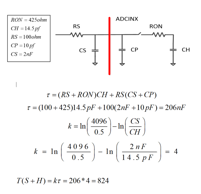
For my experiment I am using switching frequency is 50KHz and ADC sampling frequency should be 4 or 5 times larger than switching frequency. i want to design RC bucket circuit and ACQPS for 200KHZ sampling frequency. i have selected CS 2nF. is it right for 200KHZ sampling frequency? Do is need to increase or decrease CS ? I am not sure if i can increase or decrease CS as sampling frequency goes higher.  TI recommends that CS should be at least 10 or 20 times larger than CH. and how can i select RS too? I did the calculation for ACQPS is it right  or not ? I still don't understand relationship between ADC sampling and charge circuit bucket circuit

  • Hi Shah,

    Your calculations look correct. 

    Note that predicted S+H time is 825ns.  The ADC conversion time is about 215ns, so the total sample time will be a little over 1us.  If you need 4 samples per 1/50kHz this will be fast enough (but maybe you also care about latency?).  You are correct that you may want to reduce Cs to get the input to settle faster so you can sample faster.  Reducing the R-C is usually not an issue as long as you don't make C much below ~20 x Ch.  

    Selecting R is going to be based on the op-amp or other circuit driving this circuit.  How much capacitance can it drive? Increasing R increases the R-C time constant, but allows the amp/driver some isolation from the capacitive load.  Usually this is in the ballpark of 10-100 ohms.  

    The following training presentations discuss S+H design in greater depth:  https://training.ti.com/ti-precision-labs-adcs-introduction-sar-adc-front-end-component-selection

  • i have changed value of CS and RS CS=400pF and RS=50ohm( 50ohm is ok for TLV6001 OPAMP). now calculated S+H time is 162ns, so total sample time is 235ns+215=377ns.( ADC conversion time which is 215ns you mentioned is it fixed or how you found it?). Now fsample is 2.6MHZ. Is it ok for 50kHZ switchig frequency ?  i have one  more question as i told you PWM switching frequency is 50KHZ and i am using this PWM to trigger ADC SOC. so ADC frequency is same as PWM it means my ADC frequency is also 50KHZ but i have i have calculated total sampling time is 377ns they are not similar. or i need to trigger ADC with other PWM whose frequncy is same with calculated sampling time 377ns  i am confused about this  

  • Hi Shah,

    Note that the S+H time is only configurable in steps of 5ns if the SYSCLK is 200MHz, so you won't be able to exactly configure 377ns; you should round this up to 380ns.  

    You can get the exact ADC conversion time from the datasheet or TRM "ADC Timing Diagrams" section: 

    The S+H + Conversion time determine how long it takes the ADC to sample and convert after a trigger is received; you still have to trigger the ADC at whatever rate you want.  If you use a 50kHz ePWM to trigger the ADC then the sample rate will be 50kHz (and each sample will be available about 380 ns after each trigger).

    If you want to sample faster, but still synchronized with the ePWM, you can either run a 2nd ePWM at some multiple faster than the primary ePWM or you can use SOCA and SOCB from multiple sync'ed PWMs to generate multiple triggers (this second case would be used if you want the triggers at specific points in the ePWM cycle instead of evenly spaced).   

  • thank you very much i now understand

  • yes i want faster sample. so i used secondary PWM of 500KHZ switching frequency to trigger ADC then ADC sample rate is 500KHZ and my primary PWM switching frequency is 50KHZ. i am still confused that how much CS and RS i should select for 500KHZ ADC sample rate ? i have selected RS=50ohm , CS=1nF, RON = 425ohm, CP =10pF and CH = 14.5pF. now S+H time is 280ns and ACQPS is 55. and ADC conversion time is 204ns and total sample time is 280+208= 488ns. and if i select RS = 100ohm then S+H is 540ns and total sample time is 745ns  or  if i reduce RS = 10 then S+H time 80ns and total sample time will be 285ns and i think its too fast.which one is better for 500KHZ ADC samle rate? CS is 1ns is it too big?  could you please recommend me how much value of CS and RS is should select for ADC having sample rate 500KHZ. thanks  

  • Hi Shah,

    The Cs is mostly just there to prevent the driving op-amp from slewing when the sample occurs.  If external Cs is 20x the internal Ch, then the drop or spike on the pin from Cs equalizing with Ch at the beginning of the sample is not larger than 5% of the range, worst-case.  This should be small enough that the driving op-amp will be settling and not slewing, which should allow for good settling.  

    Rs is just set large enough such that the driving op-amp will not have any stability issues driving Cs and Ch.  This will be very dependent on your particular driver.

    Generally you don't want to rely on Cs and Rs for low-pass filtering.  Increasing either will result in a little more LP filtering at the expense of settling time, but if you want to add an anti-aliasing filter or other filter, you'd generally want to do that in the stage before the ADC driver.

    In general, Cs and Rs are not set based on the sampling frequency, although having a large settling time could limit which sampling frequencies can work.  Having a large settling time could also lead to increased latency, which could be a negative depending on the particular system.

    There is an alternate sizing of Cs where Cs is selected to be around 2^N x Ch (called "charge sharing").  This is used for slow sample rate signals where the driving circuit requirements are to be relaxed.  I don't think this will apply to your use case.    

  • thank you very much i saw data sheet of my particular IC it says it can drive capacitive load up to 220pf, can i use 220pf . and i also have one more question that i am using dual loop outer is voltgae loop and inner current loop and usually current loop is faster than outer loop, my current sensor ACS733 can driver capacitive load up to 220pf and RS up to 50 ohm to 1kohm. so its S+H time will short because current loop is fast so that its  sampling should be fast. while for outer voltage loop i use ISO224 isolated IC then i used TLV6001 for single ended conversion and i could not find how much RS TLV6001 can drive and CS can be 20 time CH. so its S+H can be larger. can i use different ACQPS for voltage and current loop using same ADC or do i need to power on another ADC ?  later i have seen ISO224EVM Evaluation Module  SLAU733 page 3  in which after TLV6001 ,R is selected as 47 ohm and C is selected 100pf.  is it right? 100pf is less than 20 times CH.

  • Hi Shah,

    For the drive capability of the TLV6001 you might make a different e2e thread tagged with that part number - that should route the thread to the engineers that maintain that device.  

    As far as having different S+H times, you can definitely do this on the same ADC; each SOC has separate configurable ACQPS field which controls the S+H time. 

    Alternately, using two ADCs may be preferable because the sampling can be done in parallel.  You would potentially want to use the larger of the two S+H times to ensure that the ADCs run in lock-step, as there is some performance penalty for running the ADCs async. to each other.