Tool/software: Code Composer Studio
Can someone please offer software structure suggestions on how I can realise the following for a Bi-Directional Interleaved Buck-Boost DC/DC Converter operating at 100kHz.
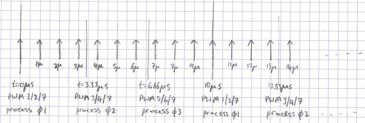
EPWM1 and EPWM2 = Phase 1 (0deg)
EPWM3 and EPWM4 = Phase 2 (120deg)
EPWM5 and EPWM6 = Phase 3 (240deg)
ADC A:
- Inductor current phase 1
- Vin
- Vout
ADC B:
- Inductor current phase 2
- Vout
- Iout
- Temp1
ADC C:
- Inductor current phase 3
- Iin
- Vother
- Temp2
Bear in mind, the above ADC arrangement cannot change as the board has been fabricated.
Requirement:
- inductor currents are required to be sampled at 900ksps
- voltages and currents are required to be sampled at 100ksps x 3
- temperature measurements are required to be sampled at 1sps
All ADC's need to be synchronised with the EPWM's and operate in a synchronous fashion.
Inductor currents are supplied to the CMPSS as part of the peak current control algorithm.
The CLA will perform the 2p2z compensation for each phase every 10us (1/100kHz).
CAN bus to operate on the CPU.
What I've done thus far:
Build configuration is set to Flash as I obtain code size errors with RAM.
CAN bus functions correctly on CPU every 10ms which uses CPU Timer1
EPWM's function correctly and are out of phase 120deg for fixed duty cycles.
Control algorithm has not been implemented at the time of writing.
I have modified the cla_ex1_adc_fir example for the ADC arrangement.
The ADC is triggering on EPWM7.
There are 3 CLA tasks plus a fourth for initialising variables.
CLA Task 1 is used for Inductor current processing (trigger on ADCA1).
CLA Task 2 is used for voltages and currents processing (trigger on ADCB1). This is where the 2p2z will be unless recommended otherwise.
CLA Task 3 is used for temperature processing (trigger on ADCC1).
I'd like input in how I can correctly initialise the ADC.