This thread has been locked.

If you have a related question, please click the "Ask a related question" button in the top right corner. The newly created question will be automatically linked to this question.

TMS320F28034: TMS320F28034 system frequency change from 60MHz to 30MHz after did surge test

Part Number: TMS320F28034

Hi Team,


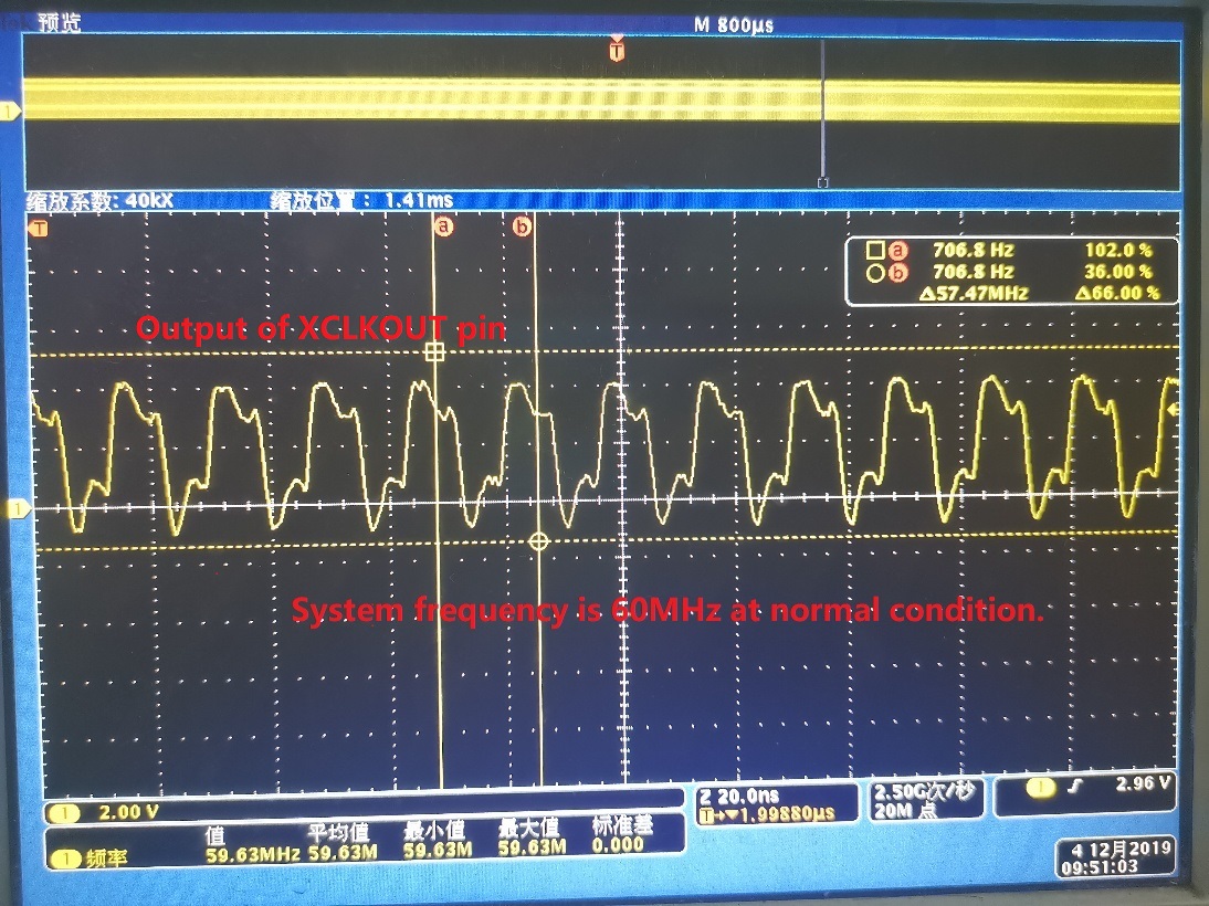
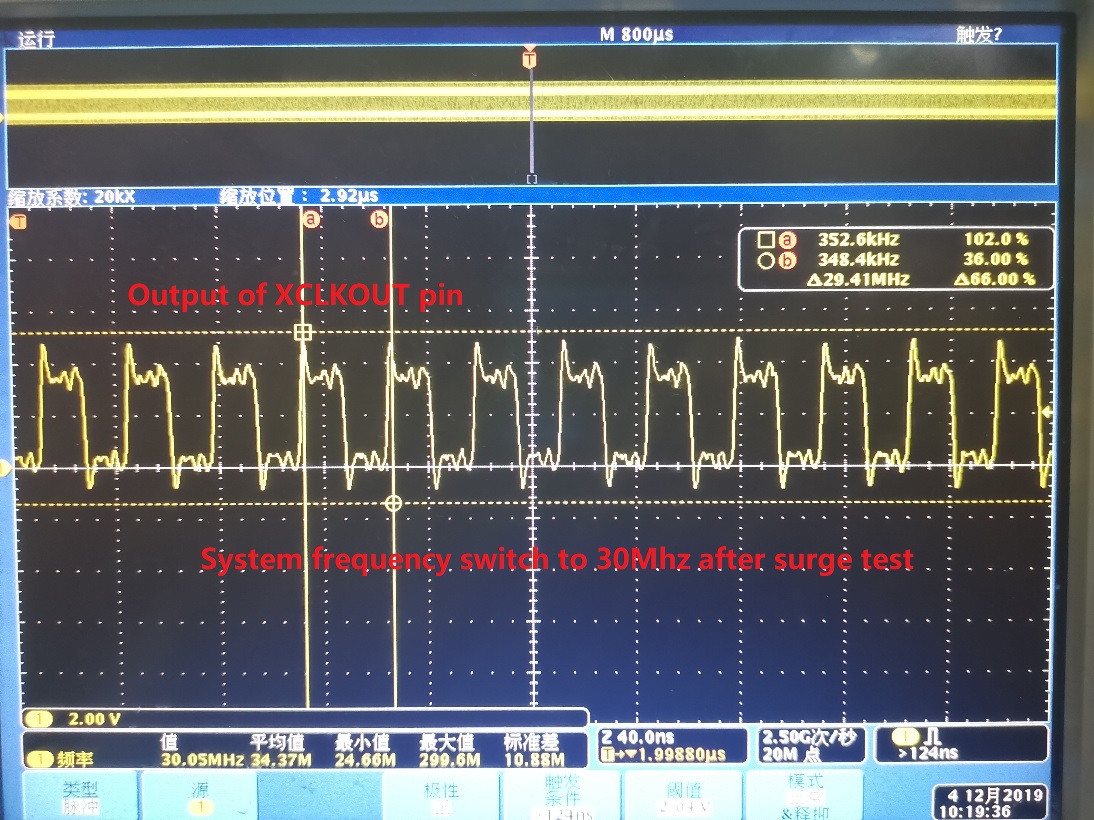
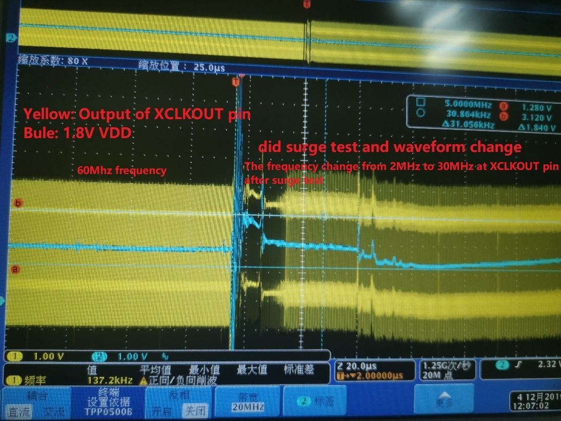
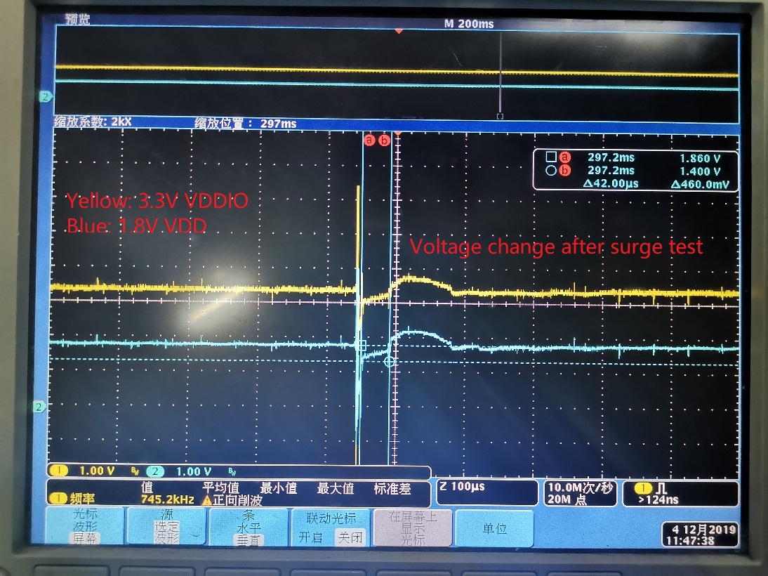
My customer did surge test on their F28034 board, they find the issue that the system frequency will change from 60Mhz to 30Mhz by monitoring XCLKOUT pin as below. actually if we look at what happen when did surge test, there will have voltage overshot at 3.3V and 1.8V as below, and the system frequency will change slowly from 2MHz to 30MHz and then stable at 30MHz. they use the internal clock without external clock circuit.

question is what happen in MCU when did the surge test? is the internal clock fail or the PLL fail?

and in such a big interference, why MCU did not reset or go to NMI interrupt but instead continue to run the code at the frequency of 30MHz, customer also monitor the output of UART communication and find the baud rate also become half of setting value.

do we have any suggestion for customer? I have review the schematic and confirm each Vddio/Vdd pin connected with 2.2uf cap and close to the pin.

  • So the system clock doesn’t simply change from 60 MHz to 30 MHz, but changes to 2 MHz first and gradually increases to 30 MHz and stops there? 

    Is the behavior exactly the same no matter how many times the test is repeated? 

    It doesn’t look like the internal clock or the PLL is “failing”. If it were to be the case, you will not see the 30 MHz output. 

    why MCU did not reset or go to NMI interrupt but instead continue to run the code at the frequency of 30MHz

    Looking at the magnitude of disturbance on both rails, it is pretty severe and violates the recommended operating conditions quoted in the datasheet. With a disturbance of this magnitude, it is hard to predict exactly what will happen to the device.

  • Hi Hareesh,

    Thanks for your support.

    It is not switch from 60MHz to 30MHz directly, but the output has a big distortion first and increase the frequency to 30MHZ, each time did the test will stable at 30MHz.

    Agree that it is pretty severe and violates the recommended operating conditions quoted in the datasheet, customer want to know what happen or what circuit inside MCU fail at such severe interference,  Could you help explain why would have this process and at last stable at 30MHz? Thanks a lot.

  • Is the test connected withe JTAG connector? If not, is there any way to get visibility to the registers related to clocking?

  • Strong,

    The system supply voltage supervisor should reset the F28034 when the supply goes outside of recommended operating conditions like this to assure proper functional operation.

    Besides the above statement, if the customer would like to debug how the 30MHz is derived then I would suggest:

    - Scope XRSn

    - Use a scope to check the clock source (is this INTOSC or X1 input?), before and after the supply violation event

    - Report all of the SYSCLK divider registers, PLL settings, and XCLKOUT divider both before and after the supply violation event

    Best regards,
    Jason

  • Strong, any updates?

  • This thread was handled/closed offline.