This thread has been locked.

If you have a related question, please click the "Ask a related question" button in the top right corner. The newly created question will be automatically linked to this question.

Compiler/TMS320F28335: EPWM Signal

Part Number: TMS320F28335
Other Parts Discussed in Thread: C2000WARE

Tool/software: TI C/C++ Compiler

I am working on the workshop example that is given by TI.

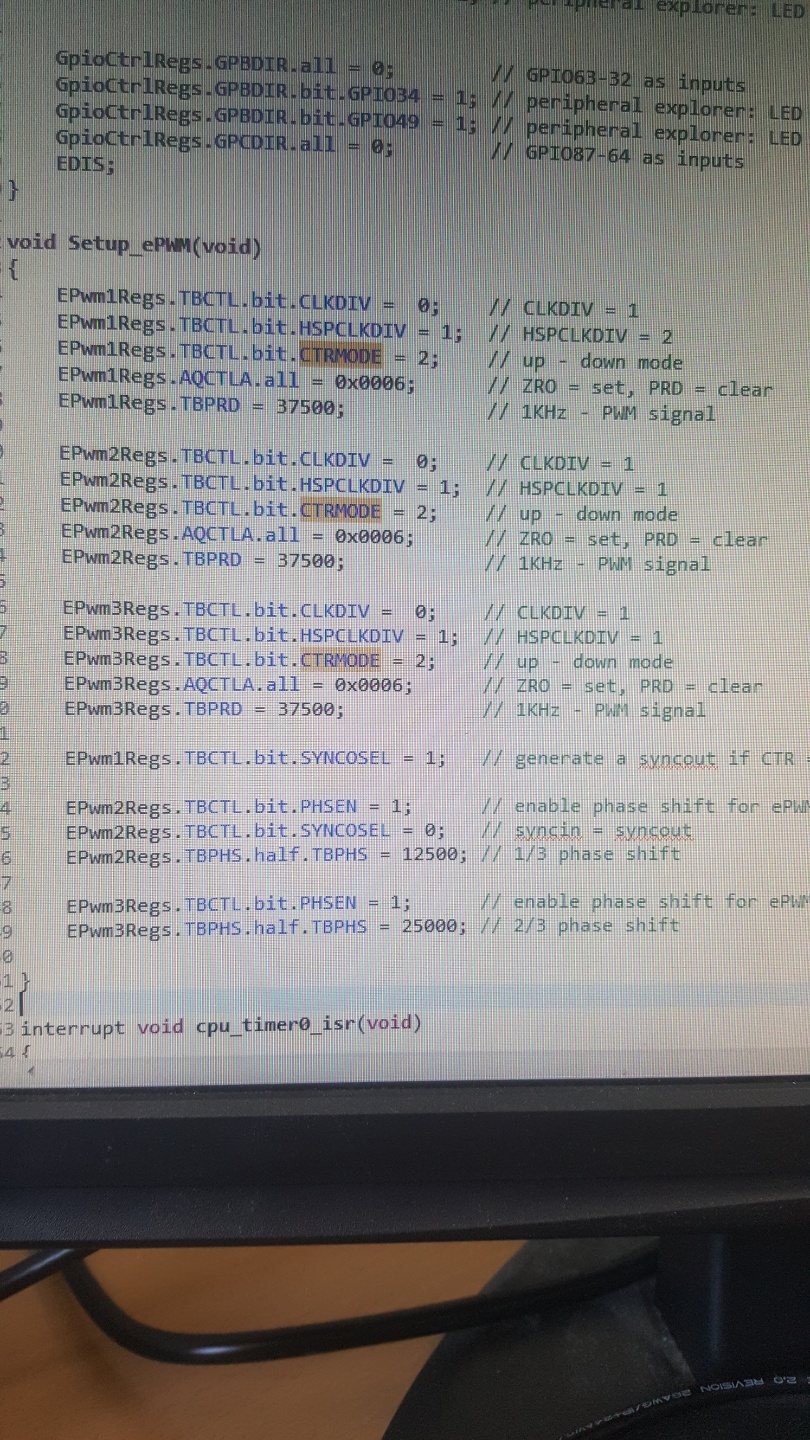
I have compiled the code for epwm generation for three-phase but :

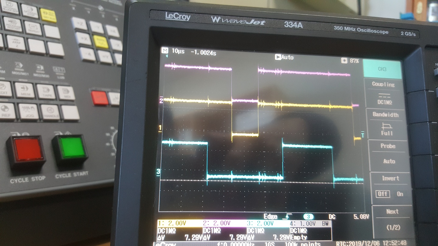
1) with changing TBPRD value nothing change across epwm output but for the same code and register values one of the epwm output has different duty cycle than other 2 (as shown in fig)

2) when I add the phase shift and debug the code again the result across epwm output is the same as before without the shift it seems that shift is not working.

I want to know about these two and I also attached the pic for proper descript of the issue

Thanks

Looking Forward

  • Muhammad,

    Could you please tell me which workshop you are using?  Also, please see the following F28335 workshop and compare your ePWM code to the lab 7 exercise solution:

    https://training.ti.com/c2000-f2833x-microcontroller-workshop?context=1137791-1137783

    I hope this helps. If this answers your question, please click the green "Verified Answer" button. Thanks.

    - Ken

  • i am working on this manual exercise Module_07.pdf

  • Muhammad,

    Thanks, the workshop you are using is from the C2000 Teaching ROM.  Also, could you please let me know which development tool you are using?  Since this workshop is very old, I am guessing that you are using the code with a newer version of CCS.  The ePWM setup code in your photo matches the solution file, however the PWM waveforms should have a 50% duty cycle (with or without the phase shift) and this does not match your photo.  Double check that you are connecting the oscilloscope to the correct ePWM1A/2A/3A outputs.  Please try running the solution file and see if you get the expected results.  Remember, if you change the TBPRD value, you should change it for all three ePMW modules.  (That is, all three should match).

    I hope this helps. If this answers your question, please click the green "Verified Answer" button. Thanks.

    - Ken

  • thanks for the response.

    I am using header file from c2000ware and compiler version Tl18.12.2 LTS with ccs9.0

    I have a double match with the solution file but the problem is still there and I also check to try with a single and three-phase epwm signal with the same TBPRD(for 1KH)  PWM Freq.

    and the second thing I want to know that when I backspace(mean remove or exclude from the debug) all the code for epwm2 and epwm3 and run the file with just epwm1  at output I can see the three epwm(epwm1,epwm2,epwm3) signal. Please guide me what the problem or issue that this happening.

    Is anything wrong that with the code 

  • Muhammad,

    First, this looks like a fundamental issue in generating the 50% duty cycle PWM waveforms, which may be caused by some other source file that is being included in C2000Ware.  The ePWM setup code is straightforward in using an up-down count mode and transitioning the ePWMxA pin on zero and period matches.  After running your code, check to make sure the register values are as expected.

    As an option, install the F28335 workshop (link in an earlier reply) and modify the solutions for Lab 7 exercise by configuring the Gpio.c file to output ePWM2A and ePWM3A (ePWM1A is already done).  Next, in Main_7.c comment out the function calls for the ADC and eCAP.  In ePWM.c replace the code with the ePWM setup code (but use the InitEPwm function name in the workshop).  This should work, and if it does then it will confirm that you have some conflict with perhaps the common code in C2000Ware.  (Note that the workshop code is self-contained and does not need to have any other software, such as C2000Ware to be installed).  Please let me know what happens.

    - Ken

  • I have tried with the workshop example and follow all the processes that u mentioned.  and at last, I got the same result,I guess some problem with my code can u please mention which area I have to double-check

  • Muhammad,

    Did you double check the values in the 'register' window after running the code?  If you can, attach your code and I will take a look.

    - Ken

  • Muhammad,

    Also, please let me know if you are using the TI F28335 Experimenter's Kit, TI F28335 Peripheral Explorer Kit, or the Spectrum Digital F28335 eZdsp Starter Kit?  In addition, let me know which header pins you have the oscilloscope connected to.

    - Ken

  • here is the code that i used:

    i am using customized board designed by my employer and thats working absolutely well so i am checking the pwm signal across gpio(0,2,4)

    #include "DSP2833x_Device.h"

    // external function prototypes
    extern void InitSysCtrl(void);
    extern void InitPieCtrl(void);
    extern void InitPieVectTable(void);
    extern void InitCpuTimers(void);
    extern void ConfigCpuTimer(struct CPUTIMER_VARS *, float, float);


    // Prototype statements for functions found within this file.
    void Gpio_select(void);
    void Setup_ePWM(void);
    interrupt void cpu_timer0_isr(void);

    //###########################################################################
    //      main code         
    //###########################################################################
    void main(void)
    {
     int counter=0; // binary counter for digital output

     InitSysCtrl(); // Basic Core Init from DSP2833x_SysCtrl.c

     EALLOW;
        SysCtrlRegs.WDCR= 0x00AF; // Re-enable the watchdog
        EDIS;   // 0x00AF  to NOT disable the Watchdog, Prescaler = 64

     DINT;    // Disable all interrupts
     
     Gpio_select();  // GPIO9, GPIO11, GPIO34 and GPIO49 as output
             // to 4 LEDs at Peripheral Explorer)

     Setup_ePWM();  // init of ePWM1, ePWM2 and ePWM3

     InitPieCtrl();  // basic setup of PIE table; from DSP2833x_PieCtrl.c
     
     InitPieVectTable(); // default ISR's in PIE

     EALLOW;
     PieVectTable.TINT0 = &cpu_timer0_isr;
     EDIS;

     InitCpuTimers(); // basic setup CPU Timer0, 1 and 2

     ConfigCpuTimer(&CpuTimer0,150,100000);

     PieCtrlRegs.PIEIER1.bit.INTx7 = 1;

     IER |=1;

     EINT;
     ERTM;

     CpuTimer0Regs.TCR.bit.TSS = 0; // start timer0

     while(1)
     {   
         while(CpuTimer0.InterruptCount == 0);
       CpuTimer0.InterruptCount = 0;
       
       //EALLOW;
       //SysCtrlRegs.WDKEY = 0x55; // service WD #1
       //EDIS;

         counter++;
       if(counter&1) GpioDataRegs.GPASET.bit.GPIO9 = 1;
        else GpioDataRegs.GPACLEAR.bit.GPIO9 = 1;
       if(counter&2) GpioDataRegs.GPASET.bit.GPIO11 = 1;
        else GpioDataRegs.GPACLEAR.bit.GPIO11 = 1;
       if(counter&4) GpioDataRegs.GPBSET.bit.GPIO34 = 1;
        else GpioDataRegs.GPBCLEAR.bit.GPIO34 = 1;
       if(counter&8) GpioDataRegs.GPBSET.bit.GPIO49 = 1;
        else GpioDataRegs.GPBCLEAR.bit.GPIO49 = 1;
     }
    }

    void Gpio_select(void)
    {
     EALLOW;
     GpioCtrlRegs.GPAMUX1.all = 0;  // GPIO15 ... GPIO0 = General Puropse I/O
     GpioCtrlRegs.GPAMUX1.bit.GPIO0 = 1; // ePWM1A active
     GpioCtrlRegs.GPAMUX1.bit.GPIO2 = 1; // ePWM2A active
     GpioCtrlRegs.GPAMUX1.bit.GPIO4 = 1; // ePWM3A active

     GpioCtrlRegs.GPAMUX2.all = 0;  // GPIO31 ... GPIO16 = General Purpose I/O
     GpioCtrlRegs.GPBMUX1.all = 0;  // GPIO47 ... GPIO32 = General Purpose I/O
     GpioCtrlRegs.GPBMUX2.all = 0;  // GPIO63 ... GPIO48 = General Purpose I/O
     GpioCtrlRegs.GPCMUX1.all = 0;  // GPIO79 ... GPIO64 = General Purpose I/O
     GpioCtrlRegs.GPCMUX2.all = 0;  // GPIO87 ... GPIO80 = General Purpose I/O
     
     GpioCtrlRegs.GPADIR.all = 0;
     GpioCtrlRegs.GPADIR.bit.GPIO9 = 1; // peripheral explorer: LED LD1 at GPIO9
     GpioCtrlRegs.GPADIR.bit.GPIO11 = 1; // peripheral explorer: LED LD2 at GPIO11


     GpioCtrlRegs.GPBDIR.all = 0;  // GPIO63-32 as inputs
     GpioCtrlRegs.GPBDIR.bit.GPIO34 = 1; // peripheral explorer: LED LD3 at GPIO34
     GpioCtrlRegs.GPBDIR.bit.GPIO49 = 1; // peripheral explorer: LED LD4 at GPIO49
     GpioCtrlRegs.GPCDIR.all = 0;  // GPIO87-64 as inputs
     EDIS;

    void Setup_ePWM(void)
    {
     EPwm1Regs.TBCTL.bit.CLKDIV =  0; // CLKDIV = 1  
     EPwm1Regs.TBCTL.bit.HSPCLKDIV = 1; // HSPCLKDIV = 2
     EPwm1Regs.TBCTL.bit.CTRMODE = 2; // up - down mode
     EPwm1Regs.AQCTLA.all = 0x0006;  // ZRO = set, PRD = clear
     EPwm1Regs.TBPRD = 37500;   // 1KHz - PWM signal

     EPwm2Regs.TBCTL.bit.CLKDIV =  0; // CLKDIV = 1  
     EPwm2Regs.TBCTL.bit.HSPCLKDIV = 1; // HSPCLKDIV = 1
     EPwm2Regs.TBCTL.bit.CTRMODE = 2; // up - down mode
     EPwm2Regs.AQCTLA.all = 0x0006;  // ZRO = set, PRD = clear
     EPwm2Regs.TBPRD = 37500;   // 1KHz - PWM signal

     EPwm3Regs.TBCTL.bit.CLKDIV =  0; // CLKDIV = 1  
     EPwm3Regs.TBCTL.bit.HSPCLKDIV = 1; // HSPCLKDIV = 1
     EPwm3Regs.TBCTL.bit.CTRMODE = 2; // up - down mode
     EPwm3Regs.AQCTLA.all = 0x0006;  // ZRO = set, PRD = clear
     EPwm3Regs.TBPRD = 37500;   // 1KHz - PWM signal
     
     EPwm1Regs.TBCTL.bit.SYNCOSEL = 1; // generate a syncout if CTR = 0

     EPwm2Regs.TBCTL.bit.PHSEN = 1;  // enable phase shift for ePWM2
     EPwm2Regs.TBCTL.bit.SYNCOSEL = 0; // syncin = syncout
     EPwm2Regs.TBPHS.half.TBPHS = 12500; // 1/3 phase shift

     EPwm3Regs.TBCTL.bit.PHSEN = 1;  // enable phase shift for ePWM3
     EPwm3Regs.TBPHS.half.TBPHS = 25000; // 2/3 phase shift

    }

    interrupt void cpu_timer0_isr(void)
    {
     CpuTimer0.InterruptCount++;
     //EALLOW;
     //SysCtrlRegs.WDKEY = 0xAA; // service WD #2
     //EDIS;
     PieCtrlRegs.PIEACK.all = PIEACK_GROUP1;
    }
    //===========================================================================
    // End of SourceCode.
    //===========================================================================

  • Muhammad,

    I have compared your code to the solutions file and it is almost exact, except you commented out servicing the watchdog with 0x55 and 0xAA.  However, at the top of main() you still have code to enable the watchdog (which was most likely disabled in CodeStartBranch.asm).  Did the solution file run "as is" on your target?  Do you have an F28335 Experimenter's Kit or Explorer Kit at the university that you can try the code on?  This would help determine if the issue is your target board or software.

    Still, at this point you are not generating the PWM waveform as configured in the code.  I suggest making the source file as simple as possible and then running a test.  Since the only purpose of this program is to configure the ePWM module - remove or comment out everything else.  That is, disable the watchdog and only keep the code to configure the three GPIO pins (ePWM1A/2A/3A), the ePWM setup function, and use a NOP in the while loop (see workshop for example).  Do not include the CPU Timer function and GPIO toggling in the while loop.  Note that this test does not require the use of interrupts, so that does not need to be configured.  All we are trying to do is just generate the waveforms.  So in summary, you will need InitSysCtrl() function, code to configure the three GPIO pins (EALLOW protected) and the code to configure the ePWM modules.  Run this test and see if the correct waveforms are being generated.

    Please let me know if this solves your problem. Also, please use the green "Verified Answer" button if your code is now working.

    - Ken

  • unfortunetly at this time i don't have experimental kit to try this code justhave this customized baord to try with...

    i follow instruction and make the code as simple as u suggst but the output result are same and one more thing i tried to check with just 1 epwmA active and debug the code and i find tht across gpio0 gpio 2 gpio 4 i am still getting the output as the gpio2 and gpio4 are disable from the code .....

    an when i disable the watchdog at start then there no output across gpio0,2,4 so thats why i enable the whatcdog at top of main: .WDCR=0x00AF..

    #include "DSP2833x_Device.h"

    extern void InitSysCtrl(void);
    extern void InitPieCtrl(void);

    void main(void)
    {

     InitSysCtrl(); // Basic Core Init from DSP2833x_SysCtrl.c

     EALLOW;
        SysCtrlRegs.WDCR= 0x00AF; // Re-enable the watchdog
        EDIS;   // 0x00AF  to NOT disable the Watchdog, Prescaler = 64

     DINT;    // Disable all interrupts
     IER=0x0000;
     IFR=0x0000;

     Gpio_select();  // GPIO9, GPIO11, GPIO34 and GPIO49 as output
             // to 4 LEDs at Peripheral Explorer)

     Setup_ePWM();  // init of ePWM1, ePWM2 and ePWM3

     InitPieCtrl();  // basic setup of PIE table; from DSP2833x_PieCtrl.c

    while(1)                           // endless loop - wait for an interrupt
         {
             asm(" NOP");

    }

    void Gpio_select(void)
    {
    asm(" EALLOW");
     //EALLOW;
     GpioCtrlRegs.GPAMUX1.all = 0;  // GPIO15 ... GPIO0 = General Puropse I/O
     GpioCtrlRegs.GPAMUX1.bit.GPIO0 = 1; // ePWM1A active

    asm("edis")

    }

    void Setup_ePWM(void)
    {
     EPwm1Regs.TBCTL.bit.CLKDIV =  0; // CLKDIV = 1
     EPwm1Regs.TBCTL.bit.HSPCLKDIV = 1; // HSPCLKDIV = 2
     EPwm1Regs.TBCTL.bit.CTRMODE = 2; // up - down mode
     EPwm1Regs.AQCTLA.all = 0x0060;  // ZRO = set, PRD = clear
     EPwm1Regs.TBPRD = 37500;   // 1KHz - PWM signal

    }

    //end of source file

  • Muhammad,

    What you are experiencing does not follow the coding in your previous reply.  When the watchdog is disabled there should be no effect on the ePWM outputs and when only one output is selected you should not see a signal on the other outputs.  Check your project and make sure that there are no other files changing the registers.  Also, power-down your target to see if that helps.

    Please try the attached file and let me know if this works.

    - Ken

    /cfs-file/__key/communityserver-discussions-components-files/171/Lab7_5F00_2_2D00_EpwmOnly.c

  • Thanks Ken,

    with disable the watchdog the system run and the output across the pwm pin is exact as we need

    This solved my issue